EPSON Stylus Scan 2500 Revision A
Operating Principles Printer Mechanism Operation 35
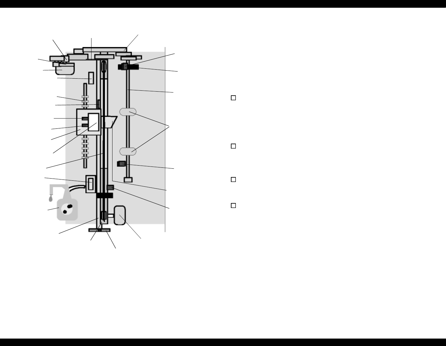
Figure 2-1. Printer Mechanism Block Diagram
2.2.1 Printing Mechanism
The basic principles of the printhead are the same as previous models; Drop-
On-Demand type MACH head method.
You need to manually input the drive-voltage code (printed on top of the
printhead) for the multi-layer piezo electric element. Input this value every
time you replace the printhead, MAIN board, or printer mechanism.
The main parts of the printhead and carriage are described below.
PZT
PZT is an abbreviation of Piezo Electric Element. The print signal is
sent from the MAIN board to the PZT via the driver circuit on the
printhead
unit. Then, the appropriate PZT squeezes the cavity, forcing
the ink stored in the cavity out through the nozzle. This process is
described in more detail on the next page.
Ink cavity
Ink flows from the ink cartridge, through the filter, and to the ink
cavity where it is stored until one of the PZT units forces it out through
the nozzles.
Nozzle Plate
The bottom surface of the printhead which contains nozzle holes to
direct ejected ink toward the paper below. See the next page.
Filter
When the ink cartridge is installed, if any dirt or dust around the
cartridge needles is absorbed into the inside of the printhead, there is
a large possibility that the nozzles will clog. Clogged nozzles can be
detected by alignment failure and dot-missing problems. To prevent
these kinds of problems, a filter is set below the cartridge needle and
ink flows through the filter on its way to the ink cavity.
PF Motor
PF motor
pinion
Intermittent
gear
73.6 Gear/Precision Gear
ASF
sensor
Detector
wheel
Loading
shaft
Loading
rollers
PE sensor
CR Motor
PG lever
CR guide shaft
Pump unit
Cap unit
Timing belt
Printhead
(one unit)
Flushing section
Star wheel
Black I/C sensor
CMY I/C sensor
Carriage unit
Disengage flag
Carriage HP
sensor
Carriage HP
sensor flag
Disengage
flag
PF roller


