EPSON Stylus Scan 2500 Revision A
Operating Principles Printer Mechanism Operation 47
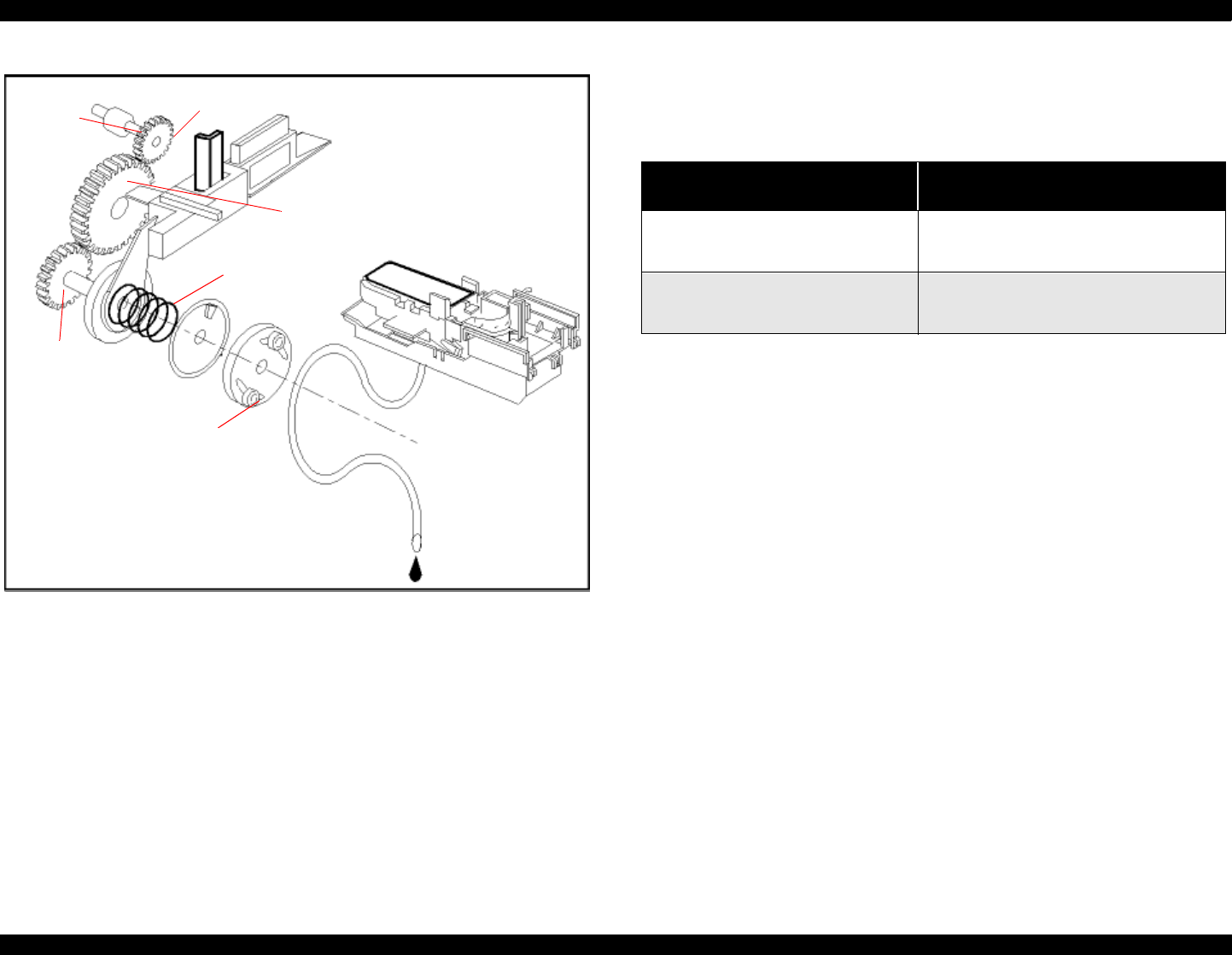
Figure 2-15. Pump Mechanism Power Transmission Process
The table below shows PF/Pump motor rotational direction and pump system
operation.
Refer to Figure 2-16 in the right column which shows the pump operations at
clockwise and counterclockwise rotation.
During ink-absorptive operations such as cleaning and flushing (but not
during normal printing), ink drains from the ink cartridge to the waste-ink
pads through the cap. During printing and flushing, ink is fired out of the
nozzles by the PZT. But during absorption operations the head is capped and
ink is sucked off the nozzle plate by the force of the vacuum created by the
pump drive and the PZT does not move.
Axis of
Paper
eject
roller
Gear A
Gear B
Gear C
Compression
spring
Pump drive
roller
Pump Motor Rotation and Function
PF motor pinion gear rotation
(looking at gear surface)
Pump unit operation
Clockwise (CW)
forward rotation
1) Release the tubes
2) Disengage Head Cleaner
3) Disengage carriage lock
Counterclockwise (CCW)
backward rotation
1) Squeeze tubes to pump ink
2) Engage Head cleaner
3) Engage carriage lock


