


EPSON Stylus Scan 2500 Revision A
Operating Principles Electrical Circuit Operating Principles 54
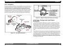
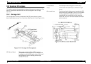
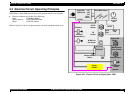
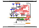
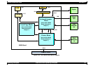
2.5 Electrical Circuit Operating Principles
EPSON Stylus Scan 2500 contains the following three electric circuit boards.
Electronic Boards for Stylus Color 2500 are;
Main: B102 Main Board
Power Supply: B102 PSB/PSE Board
Panel: B102 PNL Board
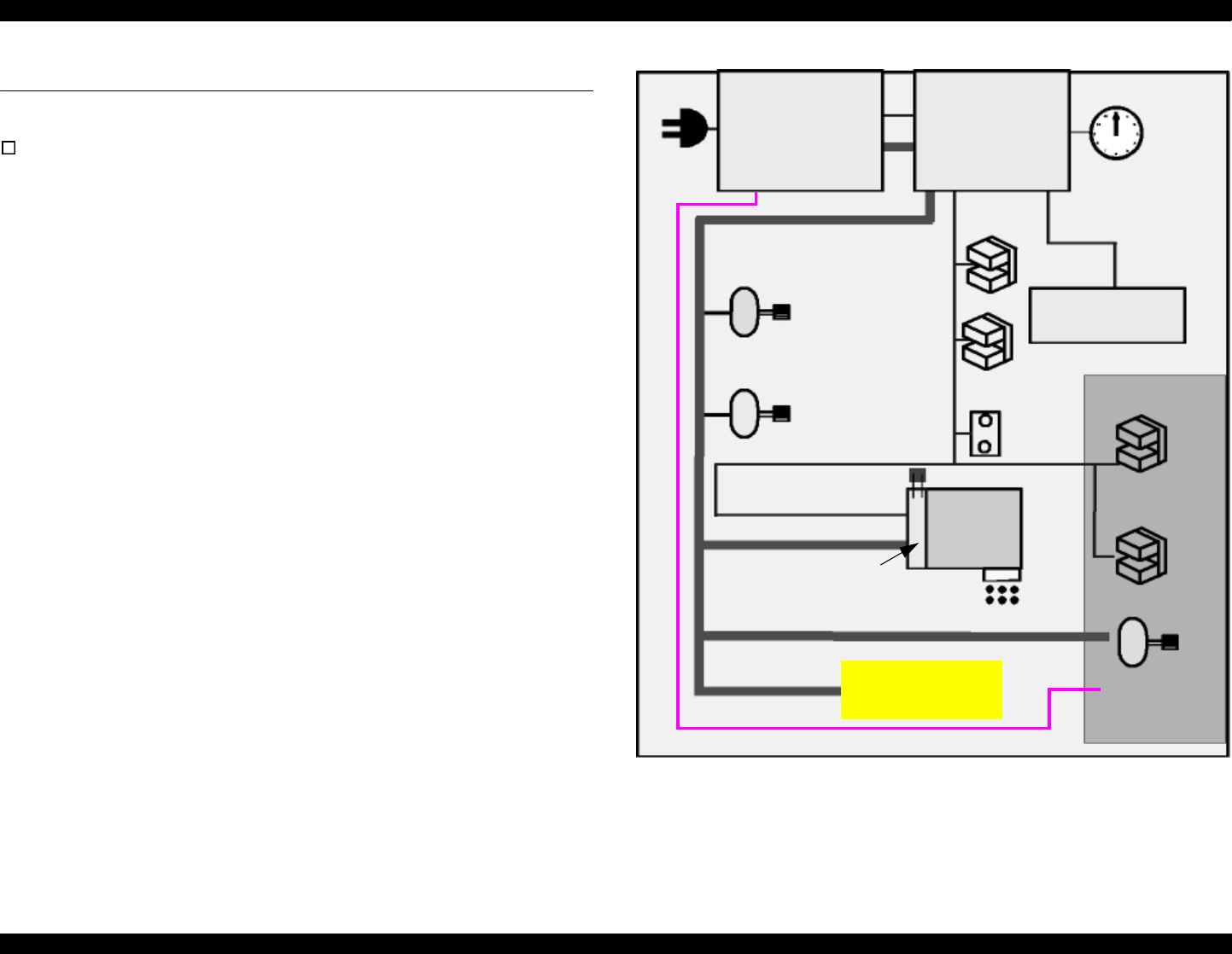
Refer to Figure 2-21 for the major connection of the 3 boards and their roles.
Figure 2-21. Electric Circuit of Stylus Color 2500
+
4
2
/
2
4
V
D
C
+
5
V
D
C
Ink End
and P-off
time
B102 MAIN Board
B102 PSB/
PSE Board
+42V/
24VDC
AC Input
CR Motor
PF Motor
(Pump Motor)
B/CMY Ink
Out Sensor
PE
Sensor
CR HP
Sensor
Thermisto
Nozzle selector
Board
Printhead
Scanner HP
Sensor
Scanner
Scanner Motor
B102
PNL
LED &
LCD
Option
+24VDC
Maintenance
Cover Sensor
CCD Sensor
+12VDC
+5VDC
+5V/
3.3V
DC
+12VDC
+
3
.
3
V
D
C