EPSON Stylus Scan 2500 Revision A
Operating Principles Printer Mechanism Operation 49
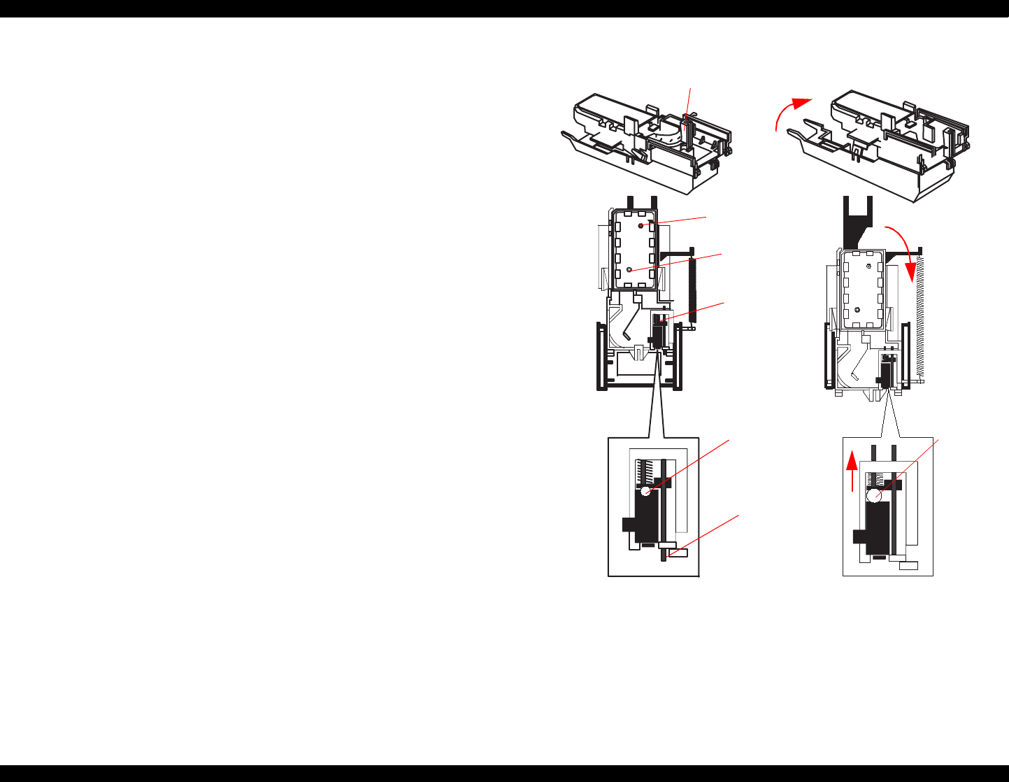
2.2.7 Cap Mechanism
The cap mechanism prevents ink from thickening and sticking on the head
surface when the printer is not in operation and it also plays a part in cleaning
the printhead. During the power-off sequence, the printhead moves to the
right where the head surface and cap come into contact, and the head surface
contacts the rubber frame of the cap surface until the power is turned back
on.
An absorber pad is spread in the cap and can hold a certain amount of ink
which is absorbed from the head without draining it to the waste ink pad.
Also, below the absorber pad, there are two valves that control the adhesion
pressure between the head and cap surface. There is also one exit and tube to
drain ink to the waste ink pads.
Position A
When the carriage is out of the HP (for example in the printable area or paper
feed position), the valves on the cap mechanism stay in Position A (closed) as
shown to the right.
Position B
When the carriage returns to the right, it catches the carriage flag on the cap
mechanism. This raises the cap to meet the head surface. This position is
used for head cleaning because the valves are still closed but the rubber
around the cap traps air, so when the pump sucks air away from the cap, a
vacuum is created and ink is sucked away from the head surface. Ink
absorption and slight ink absorption are performed in Position B.
Position C
By moving the carriage a little further to the right, the frame flag on the cap
mechanism contacts the frame and the air valve opens. When the carriage is
in this position and the pump sucks air, no ink is absorbed from the head
surface but ink left in the absorber pad in the cap is drained.
Figure 2-17. Cap mechanism and valve operation
Carriage flag
Position A Positions B and C
Ink Eject Valve
Valve
Negative Pressure
Closed-
valve state
Frame
flag
Open-valve
state


