EPSON Stylus Scan 2500 Revision A
Disassembly & Assembly Removing the Housing 86
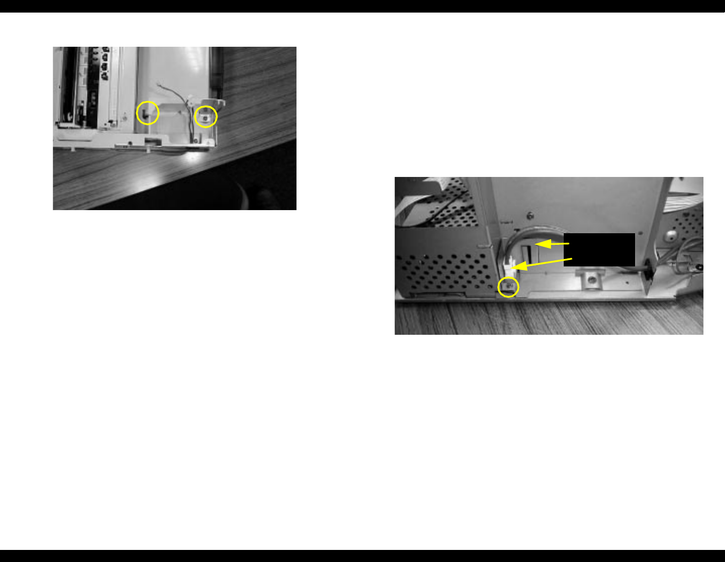
NOTE: The picture above shows the scanner home-position sensor
and maintenance cover open sensor cables still attached to
the left side frame. You can either leave them as shown above
or remove them along with the option connector cable as
describe in attached to the side frame
in “Removing the
scanner support frame” on pag e84.
5. Carefully remove the paper eject assembly to avoid scratching the surface
on any of the metal parts.
4.3.7 Removing the power supply board upper frame
1. Remove the rear cover and top cover as described in “Removing the
Housing” on page 82.
2. Remove the side covers as described in “Removing the side covers” on
page 84.
3. Remove the scanner support frame as described in “Removing the
scanner support frame” on pag e84.
4. Remove one connector for the AC cable, and one screw (CBS 3x6) and
one spacer.
Remove two screws
on the left side.
Spacer and
connector


