


Gemini User’s Manual
mg!mm
:.’ :
,. .:..:,-,’
,‘, ‘.
-
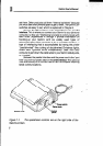
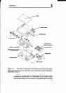
set them. Other products call them “internal switches” because
you must take their printers apart to get to them. The Gemini DIP
switches are easy to set, which is explained in Chapter 4.
Next to the DIP switches is the connector for the parallel
interface. This is where you connect your Gemini to your personal
computer, so they are “interfacing:’ and able to communicate with
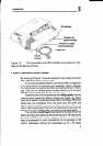
each other. (Appendices A through F provide information on
hooking-up your Gemini with six widely used types of
microcomputers.) This connector is for a “parallel” interface, a
type of interfacing that is accomplished by having the printer
“parallel-wired” like a string of double-wired Christmas lights,
where each lightbulb burns independently. Data from your
computer is sent down the cable wires to your Gemini side-by-side,
or “parallel?
Between the parallel interface and the power cord is the “port
hole” (a punch-out plastic tab) for the serialinterface. This optional
interface allows you to connect Gemini with a computer requiring
serial communications.
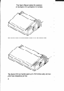
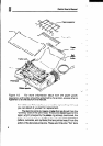
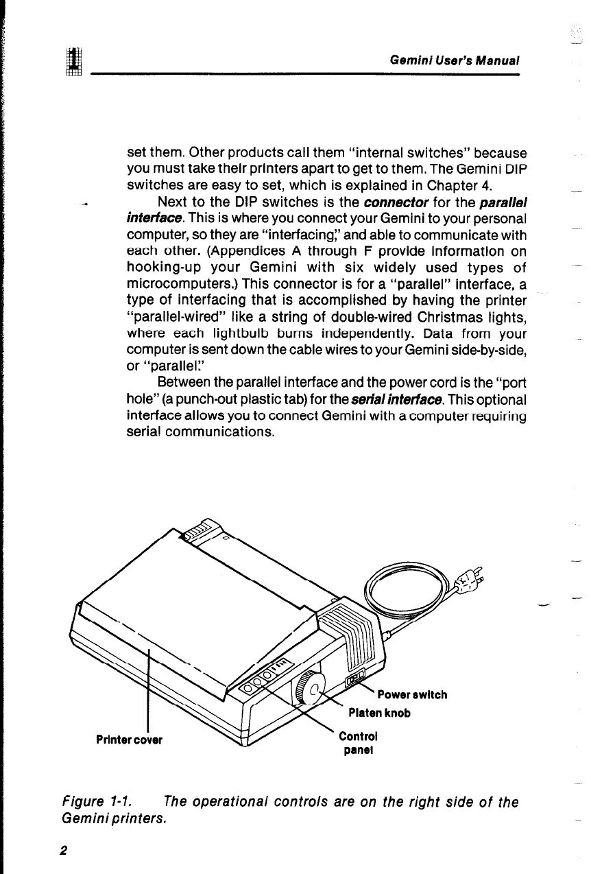
figure 1-1. The operational controls are on the right side of the
Gemini printers.
2
-
-