


THE FUNDAMENTALS OF
DOT MATRIX PRINTING
Understanding dot-matrix printing and Gemini’s graphics begins
with knowing some details about the print head and the software
that controls it. This chapter will provide you with those details.
The print head, print matrix, and vertical spacing are described in
understandable terms. The second half of this chapter will
introduce you to dot graphics: the control codes for firing the
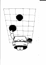
“pins:’ and a sample graphics program that will put a smile on your
paper, and perhaps on your face.
THE PRINT HEAD
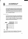
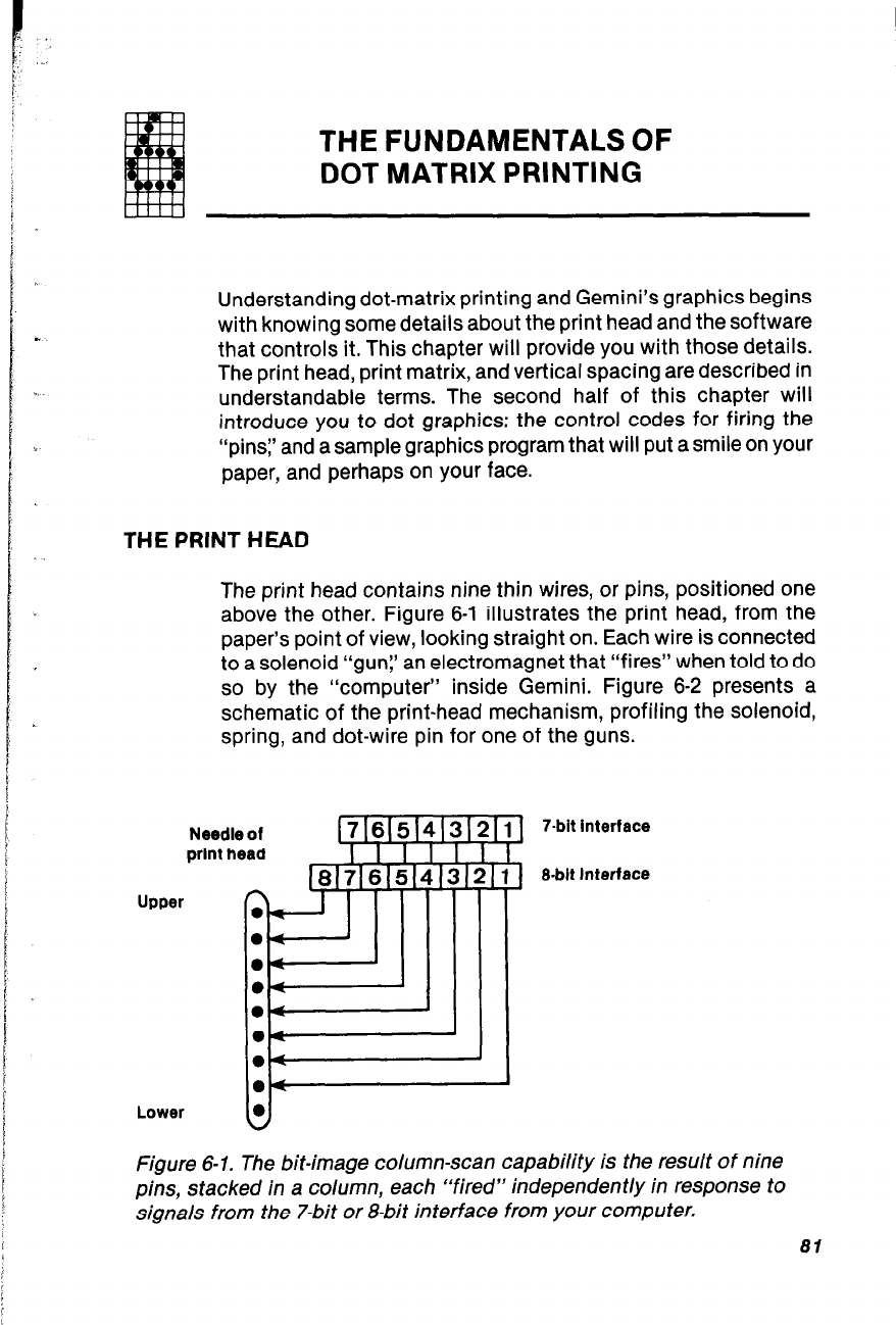
The print head contains nine thin wires, or pins, positioned one
above the other. Figure 6-1 illustrates the print head, from the
paper’s point of view, looking straight on. Each wire is connected
to a solenoid “gun;’ an electromagnet that “fires” when told to do
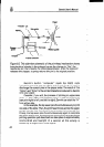
so by the “computer” inside Gemini. Figure 6-2 presents a
schematic of the print-head mechanism, profiling the solenoid,
spring, and dot-wire pin for one of the guns.
Upw
Needle of
print head
n
Lower
B==
il
7-bit interface
3
O-bit Interface
Figure 6-1. The bit-image column-scan capability is the result of nine
pins, stacked in a column, each “fired” independently in response to
signals from the 7-bit or a-bit interface from your computer.
81