


Chapter 5 Installing Additional Boards
40
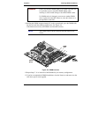
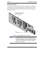
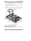
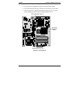
8. Remove the securing clamp from the chassis and set it aside for
re-assembly later.
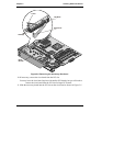
Securing Clamp
Riser Board
Figure 5-3. Riser Board and Securing Clamp
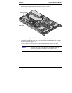
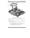
9. Lift up the latch and move the slot cover to the left away from the tabs and out of the
chassis as shown in Figure 5-4.
The PCI slot cover is held in place by the latch and must be saved for use later.
NOTE Save the slot cover for use later if the PCI board is removed.
The slot cover must be installed in the empty PCI slot to
prevent EMI interference.