


Chapter 8 Rack Mounting the HP Netserver (4-Post)
77
The screw holes cover a span of only one EIA unit, which is the height
requirement of the HP Netserver.
NOTE The Netserver can only be mounted into both holes of one EIA
Unit, but cannot be mounted across two EIA units. You cannot
use a hole in one EIA unit and a hole in another EIA unit.
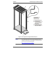
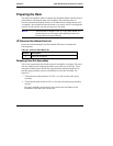
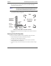
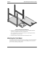
2. Use the masking tape (or marking pen) to mark above the 3rd hole up on both
front columns, as shown in Figure 8-3.
“#” represents
the EIA unit
numbers on the
rack columns.
3rd Hole
From Bottom
1st Hole
From Bottom
Masking
Tape
Maker
Bottom of
HP Netserver
Rear of
Rack
Mark this face of
the columns with
masking tape
or marker pen.
Front of
Rack
Left
Side
Right
Side
Figure 8-3. Location Marks on the Rack's Columns
3. Mark the inside face of the left-rear and right-rear rack columns as shown in
Figure 8-3.
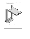
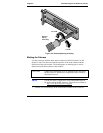
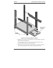
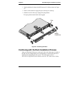
Attaching the Outer-Rail Assemblies
No tools are required to attach the outer-rail assemblies to the rack columns.
1. Pull the anti-tip foot forward out of the bottom of the rack.
See Figure 8-4 for the anti-tip foot location.
2. Lower the leveler screws on the rack's lower four corners to make firm
contact with the floor. See Figure 8-4.
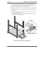
3. Align the left outer-rail to the left front and rear columns as shown in Figure
8-4.