


Chapter 5
Troubleshooting
Troubleshooting System Power
151
• The cause of this problem is not apparent from the iLO MP’s SEL or the FPL logs. If both these conditions
are true, see “System Build-Up Troubleshooting” on page 152.
Consider the following assumptions before troubleshooting system power:
• The problem is a solid failure event (it happens every time you attempt to power on the system or initiate
POST).
• There is a functioning console terminal (or a PC with appropriate terminal emulation) available and
attached to the iLO MP console port.
To perform the power-on troubleshooting procedure, follow these steps:
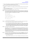
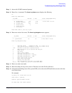
Step 1. If this is the first time the system has been powered on, check the incoming ac line voltage. Ensure
that you have 200 to 240 VAC power applied to the power supplies. The rp4410 and rp4440 servers
require 200 VAC nominal (for example, they will not operate on 100/120 VAC). Typical iLO MP SEL
entries when attempting to run on 100/120 VAC are as follows:
Alert Level 7: Fatal
Event Log Viewer Menu:
Keyword: Type-02 096f02 618242
A/C Failed, disconnected, or out of range
Logged by: Baseboard Management Controller
Sensor: Power Unit -AC Presence
Data1: 240VA Power Down
0x20430F39B1020040 FFFF026FCF090300
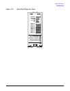
Step 2. Check the front panel power LED visible through the hole in the flap covering the power button.
• If it is flashing amber, housekeeping voltages are available. Go to step 3.
• If it is not illuminated or flashing, housekeeping voltages are not available. Check the LEDs on
the power supplies. The power supplies have three LED indicators: a Predict Fail amber LED to
the left, a Failed amber LED in the center (a triangle with an exclamation point), and a green
Power LED to the right. If the Failed LED is illuminated, you must replace the power supply. If
the green Power LED is illuminated or flashing, the supply is OK and has ac voltage applied.
Step 3. Verify whether the iLO MP is functional.
The iLO MP is typically accessed through a terminal attached to the iLO MP LAN port on the rear
bulkhead using a Ctrl-B CR key sequence. If the iLO MP is functional, check the status of the dc
power system using the CM> PC command or the CM> PS command. If the PC or PS command output
shows the current system power state to be off, try to turn the dc power ON using the PC command.
If the system does not turn the dc power on, or if it does not remain on, check the SEL for errors as
described below. Alternatively, you can press the power button (located behind the front bezel flap)
to attempt to enable the dc voltages.
Step 4. If a terminal attached to the iLO MP LAN port does not respond to a
Ctrl-B CR key sequence (and
the terminal is running at 9600 baud, 8 data bits, No Parity, 1 Stop Bit, Xon/Xoff, and is online), the
iLO MP might be hung or nonfunctional. Check the following LEDs located inside the system:
• The iLO MP heartbeat LED.
This green LED is located between the 3.3 and 5 volt VRMs on the I/O baseboard assembly and