


Chapter 6
Removing and Replacing Components
Removing and Replacing PCI/PCI-X Cards
227
Step 1. If rack-mounted, slide the server out from the rack until it stops. (See “Accessing a Rack-Mounted
Server” on page 177.)
Step 2. Remove the top cover. (See “Removing the Top Cover” on page 182.)
Step 3. Disconnect all external and internal cables attached to the PCI card in the side service bay.
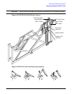
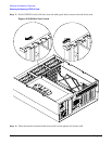
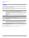
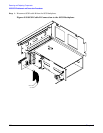
Step 4. Turn the PCI/PCI-X card latch on the chassis to approximately 45 degrees clockwise to free the
MRL. (Figure 6-27)
Step 5. Pull up on the MRL until it stops.
Step 6. Turn the PCI/PCI-X card latch another 45 degrees clockwise to completely expose the PCI-PCI-X
card bulkhead. (Figure 6-27)
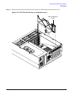
Step 7. If the PCI/PCI-X card is full size, open the slider gate bracket to enable PCI/PCI-X card removal.
(Figure 6-39)
Step 8. Remove the card from the slot by grasping the top edges of the card and pulling up. The notches in
the OLX dividers provide access to the PCI card for removal.
Installing a PCI Card Offline
To replace a PCI card with the server power off, follow these steps:
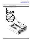
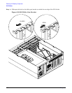
Step 1. Insert the card into the appropriate slot. (Figure 6-26)
Step 2. Turn the PCI/PCI-X card latch on the chassis approximately 45 degrees counterclockwise to enable
closing of the MRL. (Figure 6-27 and Figure 6-28)
Step 3. Push down on the MRL until it stops against the chassis wall. (Figure 6-27)
Step 4. Turn the PCI/PCI-X card latch on the chassis another 45 degrees counterclockwise to lock the
PCI/PCI-X card into position.
Step 5. If the PCI/PCI-X card is full size, close the slider gate bracket to secure the card. (Figure 6-30)
Step 6. Reconnect all internal and external cables to the PCI/PCI-X card.
Step 7. Replace the top cover. (See “Replacing the Top Cover” on page 183.)
Step 8. Slide the server all the way back into the rack until it stops.
Step 9. Turn on power by plugging the ac power cords into power supply units.