


Chapter 6
Removing and Replacing Components
Midplane Riser Board
255
Step 7. Replace the memory extender board. (See “Replacing the Memory Extender Board” on page 186.)
Step 8. Replace the front cover. (See “Replacing the Front Cover” on page 182.)
Step 9. Replace the front bezel. (See “Replacing the Front Bezel” on page 180.)
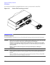
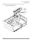
Midplane Riser Board
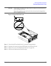
The midplane riser board is attached to the main bulkhead in the center of the chassis.
WARNING Ensure that the system is powered off and all power sources have been disconnected
from the server before removing or replacing the midplane riser backplane.
Voltages are present at various locations within the server whenever an ac power
source is connected. This voltage is present even when the main power switch is in
the off position.
Failure to observe this warning can result in personal injury or damage to
equipment.
CAUTION Failure to properly complete the steps in this procedure results in erratic system behavior or
system failure. For assistance with this procedure contact your local HP Authorized Service
Provider.
Observe all ESD safety precautions before attempting this procedure. Failure to follow ESD
safety precautions can result in damage to the server.
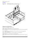
Removing the Midplane Riser Board
To remove the midplane riser board, follow these steps:
Step 1. If rack-mounted, slide the server out from the rack until it stops. (See “Accessing a Rack-Mounted
Server” on page 177.)
Step 2. Remove the front bezel. (See “Removing the Front Bezel” on page 180.)
Step 3. Remove the front and top covers. (See “Front and Top Covers” on page 181.)
Step 4. Remove the memory extender board. (See “Removing a Memory Extender Board” on page 184.)
Step 5. Remove the processor extender board. (See “Removing the Processor Extender Board” on page 192.)
Step 6. Remove the three chassis fan units. (See “Hot-Swappable Chassis Fan Unit” on page 203.)
Step 7. Remove the I/O baseboard assembly. (See “Removing the I/O Baseboard Assembly” on page 207.)
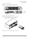
Step 8. Remove the SCSI duplex board from the SCSI backplane. (See “Removing the SCSI Duplex Board”
on page 233.)
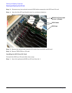
Step 9. Remove the SCSI backplane. (See “Removing the SCSI Backplane” on page 253.)
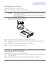
Step 10. Unplug the power distribution board power cable and signal cable from the midplane riser board.