


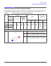


System Specifications
Environmental Specifications
Chapter 2
51
Cooling
This section provides information on the cooling systems in the server.
CPU and Memory Cooling
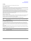
The server incorporates front to back airflow across the processor and memory extender boards and through
the HDD backplane. Two 127 mm dual fan assemblies, mounted vertically in the center of the chassis, pull air
through the processor and memory section and push air through the PCI section.
Each processor and memory dedicated dual fan assembly is controlled by smart fan control circuits embedded
in the system I/O board. The smart fan control circuit receives fan control input from the system fan
controller in the I/O board, and returns fan status information to the system fan controller. The smart fan
circuit controls the power and the pulse-width-modulated control signal to the fan and monitors the speed
indicator back from each of the fans. The fan status LED is driven by the smart fan circuit. The fan status
LED is located on the diagnostic board inside the system.
Bulk Power Supply Cooling
Cooling for the bulk power supplies is provided by one 120 mm dual fan assembly and one externally mounted
60 mm power supply fan. Air is pushed into both power supply bays by the 120 mm fan assembly and
exhausted out the rear by the 60 mm fan (one per power supply).
Air flows out of the rear of the chassis with minimal leakage into the cell airflow plenum.
NOTE A power supply filler is required in the unused power supply slot to maintain proper airflow
throughout the system.
PCI and Mass Storage Section Cooling
Two dual fan assemblies located at the center of the chassis provide airflow for all the PCI slots. Airflow is
over the processor and memory extender boards and into the PCI section. The fans are controlled by the
system temperature and run at the speed necessary to maintain proper internal temperature throughout the
chassis.
The air is pulled through openings in the front cover and the mass storage devices and pushed through the
PCI card cage.
Perforation is provided between and above the PCI card cage to enable proper exhaust ventilation to maintain
the required temperature rating of the PCI cards.
CAUTION For maximum cooling effects, ensure that the chassis ventilation holes are not blocked or
covered after installation.