


Installing the System
Installing Additional Components
Chapter 3
80
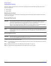
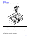
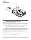
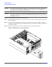
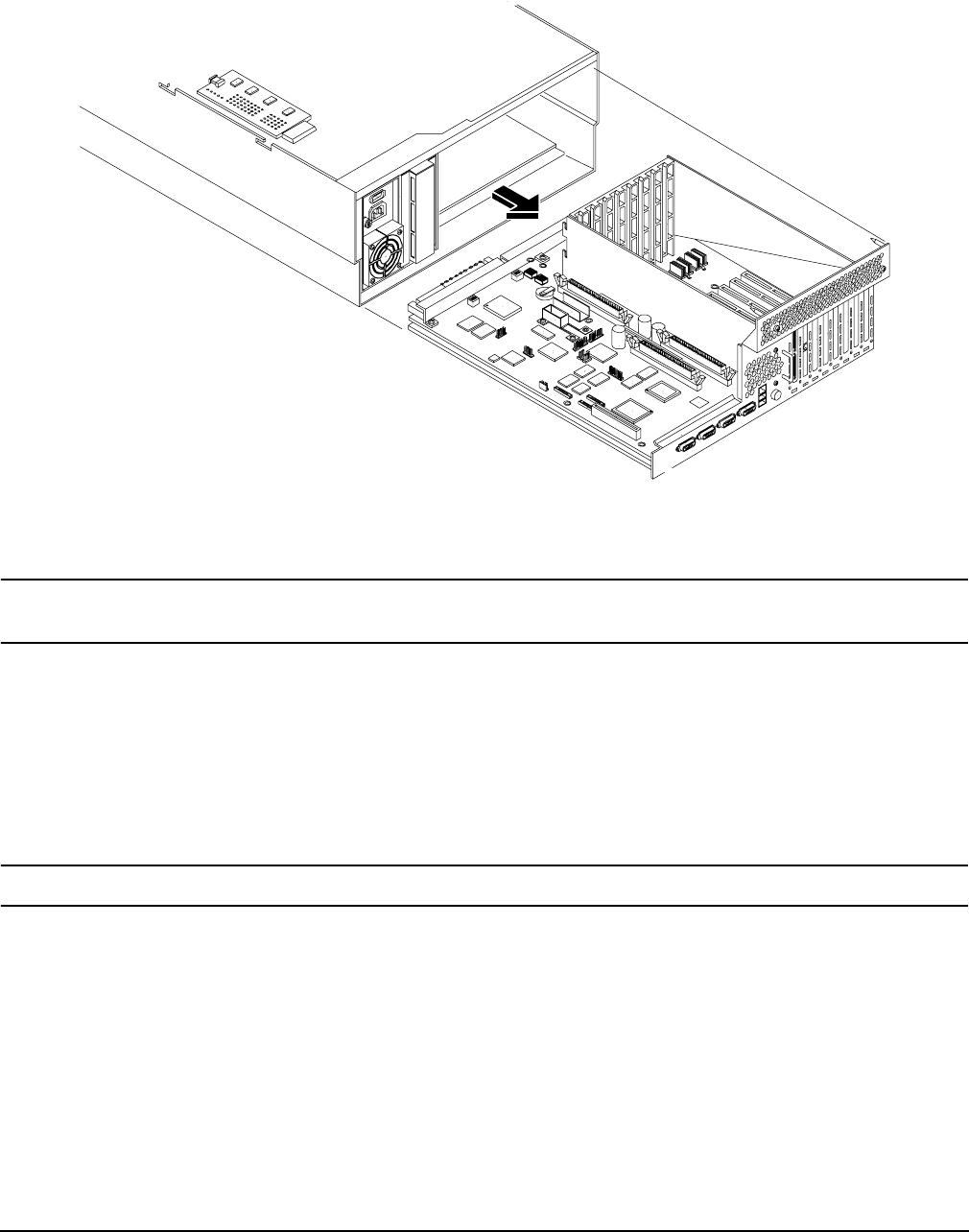
Figure 3-17 I/O Baseboard Assembly Removal
Replacing the I/O Baseboard Assembly
NOTE The I/O baseboard assembly replacement procedure assumes that you are reinstalling the
assembly that was previously removed from a configured server.
To replace the I/O baseboard assembly, follow these steps:
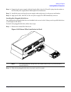
Step 1. Ensure that all fan modules are removed from the chassis before sliding in the I/O baseboard
assembly or the fans and the I/O baseboard can be damaged
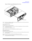
Step 2. Align the I/O baseboard assembly rails with the chassis slots and slide the assembly into the
chassis until it stops against the midplane riser board socket. Ensure the I/O baseboard locking
lever is in the up position to engage correctly with the midplane riser board socket.
CAUTION The I/O baseboard assembly is large. Use care when sliding it into the server chassis.
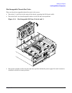
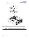
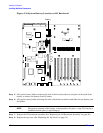
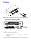
Step 3. With the I/O baseboard flush against the midplane riser board socket, push down firmly on the
locking lever until the I/O baseboard plugs all the way into the midplane riser board socket and the
locking lever clicks into place on the chassis wall. (Figure 3-16)
Step 4. Replace the three chassis fan units. (See “Replacing a Hot-Swappable Fan Unit” on page 77.)
Step 5. Plug all external cabling into the ports at the rear of the chassis.
Step 6. Plug the internal SCSI cables into the HBA board in PCI slot 1.
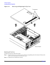
Step 7. Replace the top cover. (See “Replacing the Top Cover” on page 74.)