


Chapter 6
Removing and Replacing Components
Display Board
267
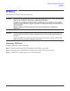
Step 7. Replace the front bezel. (See “Replacing the Front Bezel” on page 180.)
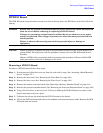
Display Board
The display board is located behind the control panel under the front cover. The display board contains the
server power button and three LEDs that indicate server status.
WARNING Ensure that the system is powered off and all power sources have been disconnected
from the server before removing or replacing the display board.
Voltages are present at various locations within the server whenever an ac power
source is connected. This voltage is present even when the main power switch is in
the off position.
Failure to observe this warning can result in personal injury or damage to
equipment.
CAUTION Failure to properly complete the steps in this procedure results in erratic system behavior or
system failure. For assistance with this procedure, contact your local HP Authorized Service
Provider.
Observe all ESD safety precautions before attempting this procedure. Failure to follow ESD
safety precautions can result in damage to the server.
Removing the Display Board
To remove the display board, follow these steps:
Step 1. If rack-mounted, slide the server out from the rack until it stops. (See “Accessing a Rack-Mounted
Server” on page 177.)
Step 2. Remove the front bezel. (See “Removing the Front Bezel” on page 180.)
Step 3. Remove the front cover. (See “Removing the Front Cover” on page 181.)
Step 4. Remove the memory extender board. (See “Removing a Memory Extender Board” on page 184.)
Step 5. Remove the processor extender board. (See “Removing the Processor Extender Board” on page 192.)
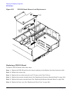
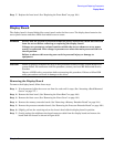
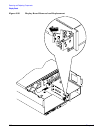
Step 6. Slightly pull out the retaining tab on the chassis that holds the display board in position.
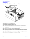
Step 7. Gently unplug the midplane riser board connector cable from the display board and remove the
board from the chassis as shown in Figure 6-56.