


Chapter 6
Removing and Replacing Components
Processor Extender Board
195
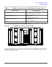
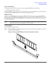
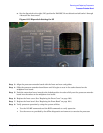
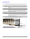
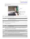
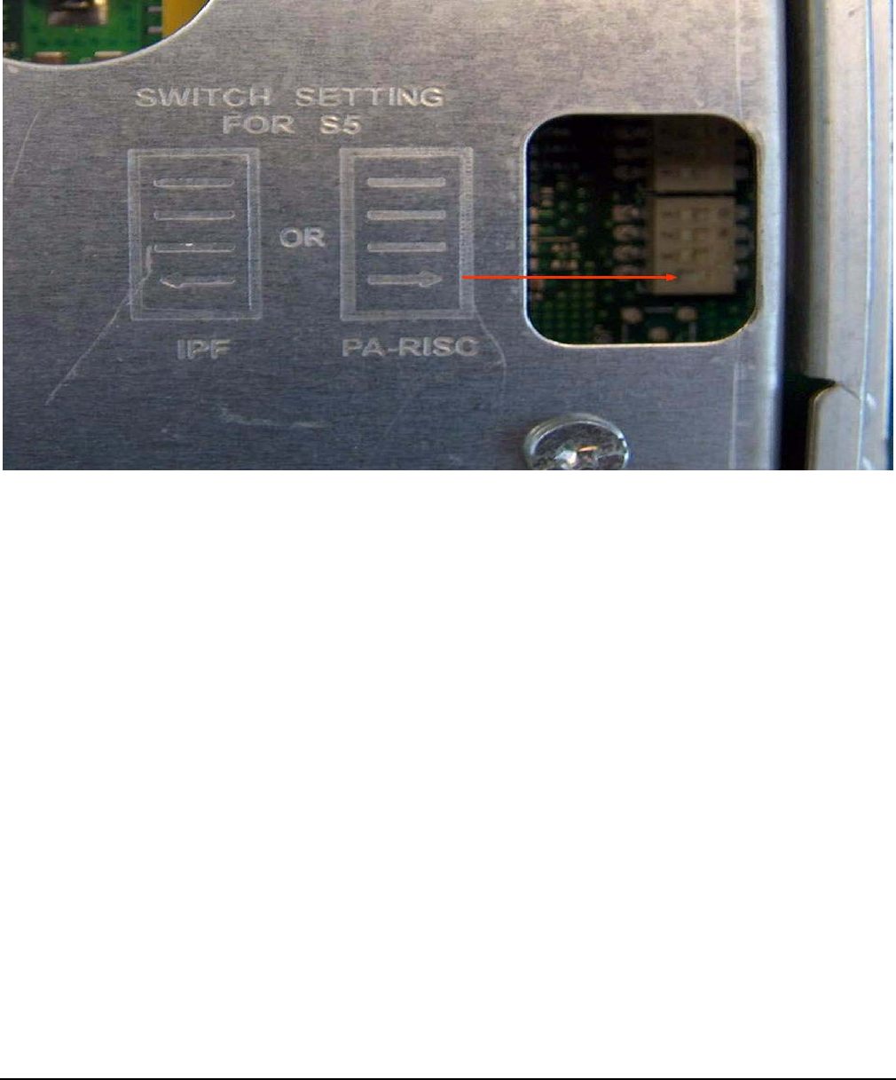
a. Set the dipswitch to the right (ON) position for PA-RISC. Do not disturb switch banks 1 through
4 beneath the sheet metal.
Figure 6-13 Dipswitch Setting for S5
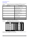
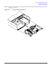
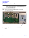
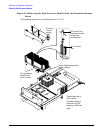
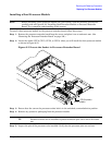
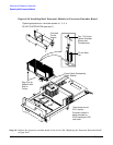
Step 3. Align the processor extender board with the front and rear card guides.
Step 4. Slide the processor extender board down until it begins to seat in the socket located on the
midplane riser board.
Step 5. Push the extraction levers inward to the locked position in order to fully seat the processor extender
board into the socket on the midplane riser board.
Step 6. Replace the front cover. (See “Replacing the Front Cover” on page 182.)
Step 7. Replace the front bezel. (See “Replacing the Front Bezel” on page 180.)
Step 8. Verify processor operation by using the system utilities.
• Use the iLO MP commands and the BCH commands to verify operation.
•Use the MAKODIAG provided by the offline diagnostic environment to exercise the processor.