


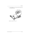
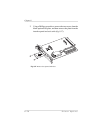
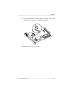
7. Examine the ends of the two plastic support posts that come
with the daughterboard: one end has a slightly larger diameter
and the other end is slightly more tapered. Insert the larger
ends into the controller board.
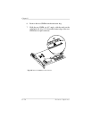
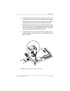
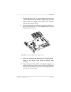
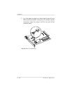
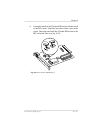
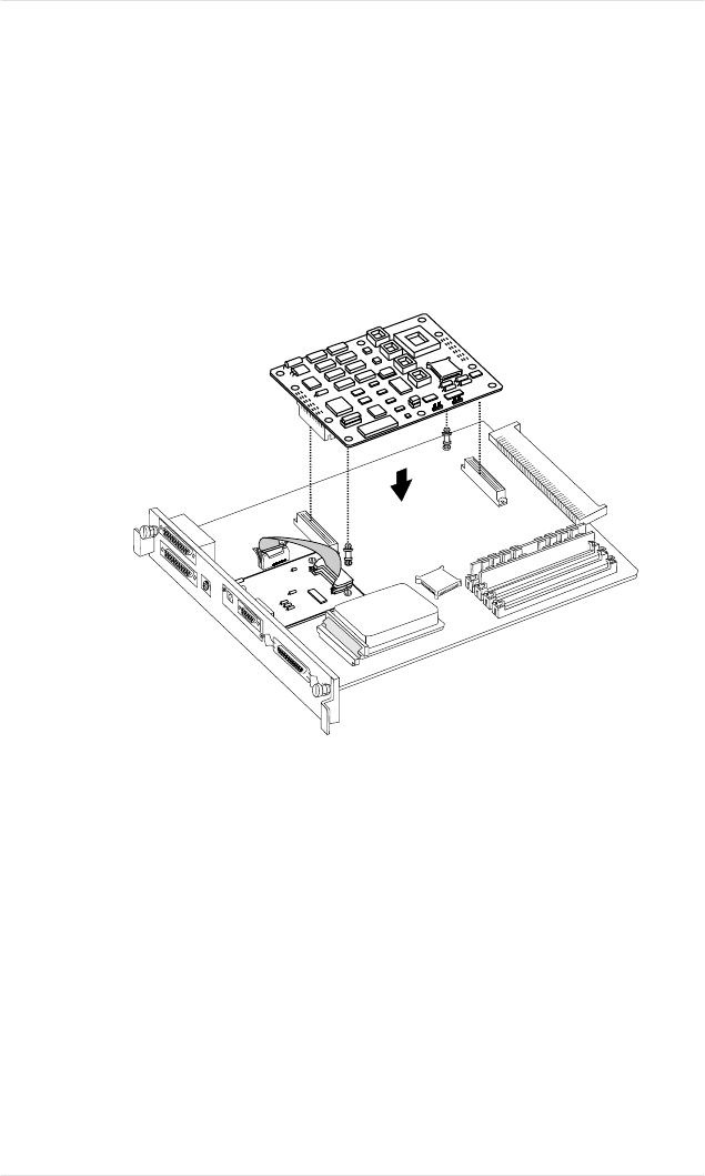
8. Attach the daughterboard to the two support posts and the two
48-pin connectors (fig. 8.20). (The daughterboard is keyed so
that it fits only one way.)
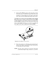
9. Follow the instructions in “Replacing the Controller Board”
(earlier in this chapter), being careful to eliminate static
electricity.
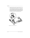
10. If your interface kit came with an external power supply box,
attach it to the round connector next to the network interface
port; then connect the box to a power cord and plug the power
cord into an electrical outlet.
Fig. 8.20 Attach the Daughterboard to Support Posts
Chapter 8
Printer Options 8-31