


Functional Description
R
Intel
®
82845 MCH for SDR Datasheet 109
5.2 System Memory Interface
The 845 chipset can be configured to support PC133 SDRAM.
5.2.1 Single Data Rate (SDR) SDRAM Interface Overview
The MCH integrates a system memory SDRAM controller with a 64-bit wide interface and twelve
system memory clock signals (each at 133 MHz). The MCH’s system memory buffers support
LVTTL (SDRAM) signaling at 133 MHz.
The MCH includes support for:
• Up to 3 GB of 133 MHz SDR SDRAM
• PC133 unbuffered 168 pin SDR SDRAM DIMMs
• Maximum of 3 DIMMs, single-sided and/or double-sided
•
Configurable optional ECC
The two bank-select lines SBS[1:0] and the thirteen address lines (SMA[12:0]) allow the MCH to
support 64-bit wide DIMMs using 64 Mb, 128 Mb, 256 Mb, and 512 Mb SDRAM technologies.
While address lines SMA[9:0] determine the starting address for a burst, burst lengths are fixed at
four. Twelve chip selects SCS# lines allow a maximum of three rows of single-sided SDRAM
DIMMs and six rows of double-sided SDRAM DIMMs.
The MCH’s system memory controller targets CAS latencies of 2 and 3 clocks for SDRAM. The
MCH provides refresh functionality with a programmable rate (normal SDRAM rate is
1 refresh/15.6 us).
5.2.2 Memory Organization and Configuration
In the following discussion the term row refers to a set of memory devices that are simultaneously
selected by a SCS# signal. The MCH supports a maximum of 6 rows of memory. For the purposes
of this discussion, a “side” of a DIMM is equivalent to a “row” of SDRAM devices.
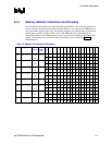
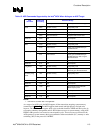
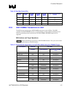
Table 12. Supported DIMM Configurations
Density 64 Mbit 128 Mbit 256 Mbit 512 Mbit
Device
Width
X8 X16 X8 X16 X8 X16 X8 X16
Single \
Double
SS/DS SS/DS SS/DS SS/DS SS/DS SS/DS SS/DS SS/DS
168 pin
SDR
DIMMs
64 MB /
128 MB
32 MB /
64 MB
128 MB /
256 MB
64 MB /
128 MB
256 MB /
512 MB
128 MB /
256 MB
512 MB /
1024 MB
256 MB /
512 MB