Register Description
R
56 Intel
®
82845 MCH for SDR Datasheet
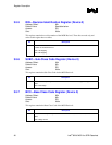
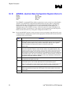
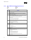
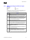
3.5.18 DRC—DRAM Controller Mode Register (Device 0)
Offset: 7C–7Fh
Default: 00000000h
Access: R/W, RO
Size: 32 bits
Bit Description
31:30 Revision Number (REV)—R/W. Reflects the revision number of the format used for SDRAM
register definition. Currently, this field must be 00, since this revision (rev 00) is the only existing
version of the specification.
29 Initialization Complete (IC)—R/W. This bit is used for communication of software state
between the memory controller and the BIOS. BIOS sets this bit to 1 after initialization of the
DRAM memory array is complete.
28 Dynamic Powerdown Mode Enable—R/W. When set, the system memory controller will put a
pair of rows into powerdown mode when all banks are pre-charged (closed). Once a bank is
accessed, the relevant pair of rows is taken out of powerdown mode.
The entry into powerdown mode is performed by de-activation of CKE. The exit is performed by
activation of CKE.
0 = Disable. System memory powerdown disabled
1 = Enable. System memory powerdown enabled
Note: Dynamic powerdown is a mobile only feature and not supported on desktop applications.
27:24 Active SDRAM Rows—R/W. Implementations may use this field to limit the maximum number
of SDRAM rows that may be active at once.
0000 = All rows allowed to be in the active state
Others = Reserved.
23:22 Reserved.
21:20 DRAM Data Integrity Mode (DDIM)—R/W. These bits select the system memory data integrity
mode.
00 = Non-ECC mode
10 = Error checking with correction
Other = Reserved
19:11 Reserved.
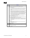
10:8 Refresh Mode Select (RMS)—R/W. This field determines whether refresh is enabled and, if
so, at what rate refreshes will be executed.
000 = Reserved
001 = Refresh enabled. Refresh interval 15.6 us
010 = Refresh enabled. Refresh interval 7.8 us
011 = Refresh enabled. Refresh interval 64 us
111 = Refresh enabled. Refresh interval 64 clocks (fast refresh mode)
Other = Reserved
7 Reserved.


