


Register Description
R
Intel
®
82845 MCH for SDR Datasheet 89
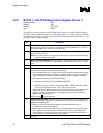
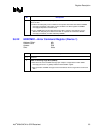
3.6.16 SSTS1—Secondary PCI-PCI Status Register (Device 1)
Address Offset: 1E–1Fh
Default Value: 02A0h
Access: RO, R/WC
Size: 16 bits
SSTS1 is a 16-bit status register that reports the occurrence of error conditions associated with
secondary side (i.e., AGP side) of the “virtual” PCI-PCI bridge embedded in the MCH.
Bit Descriptions
15 Detected Parity Error (DPE1)—R/WC.
0 = Software sets this bit to 0 by writing a 1 to it.
1 = MCH detected a parity error in the address or data phase of AGP bus transactions.
14 Reserved.
13 Received Master Abort Status (RMAS1)—R/WC.
0 = Software sets this bit to 0 by writing a 1 to it.
1 = MCH terminated a Host-to-AGP with an unexpected master abort.
12 Received Target Abort Status (RTAS1)—R/WC.
0 = Software sets this bit to 0 by writing a 1 to it.
1 = MCH-initiated transaction on AGP is terminated with a target abort.
11 Signaled Target Abort Status (STAS1)—RO. Hardwired to a 0. The MCH does not generate
target abort on AGP.
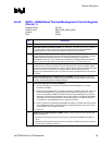
10:9 DEVSEL# Timing (DEVT1)—RO. Hardwired to 01. This 2-bit field indicates the timing of the
DEVSEL# signal when the MCH responds as a target on AGP. This field indicates the time
when a valid DEVSEL# can be sampled by the initiator of the PCI cycle.
01 = Medium timing.
8 Master Data Parity Error Detected (DPD1)—RO. Hardwired to 0. MCH does not implement
G_PERR# signal.
7 Fast Back-to-Back (FB2B1)—RO. Hardwired to 1. MCH as a target supports fast back-to-back
transactions on AGP.
6 Reserved.
5 66 MHz Capable (CAP66)—RO. Hardwired to 1. AGP bus is capable of 66 MHz operation.
4:0 Reserved.