


LGA1155 Socket
24 Thermal/Mechanical Specifications and Design Guidelines
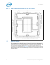
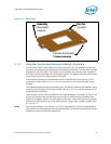
Cover retention must be sufficient to support the socket weight during lifting,
translation, and placement (board manufacturing), and during board and system
shipping and handling. PnP Cover should only be removed with tools, to prevent the
cover from falling into the contacts.
The socket vendors have a common interface on the socket body where the PnP cover
attaches to the socket body. This should allow the PnP covers to be compatible between
socket suppliers.
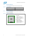
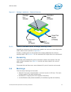
As indicated in Figure 3-6, a Pin 1 indicator on the cover provides a visual reference for
proper orientation with the socket.
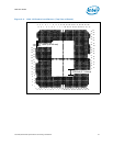
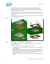
3.4 Package Installation / Removal
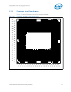
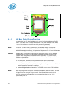
As indicated in Figure 3-7, access is provided to facilitate manual installation and
removal of the package.
To assist in package orientation and alignment with the socket:
• The package Pin1 triangle and the socket Pin1 chamfer provide visual reference for
proper orientation.
• The package substrate has orientation notches along two opposing edges of the
package, offset from the centerline. The socket has two corresponding orientation
posts to physically prevent mis-orientation of the package. These orientation
features also provide initial rough alignment of package to socket.
• The socket has alignment walls at the four corners to provide final alignment of the
package.
Figure 3-6. Pick and Place Cover
Pick & Place Cover
Pin 1
ILM Installation
Pick & Place Cover
Pin 1
ILM Installation