


Thermal/Mechanical Specifications and Design Guidelines 95
Mechanical Drawings
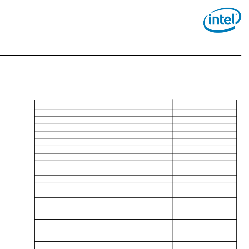
B Mechanical Drawings
Table B-1 lists the mechanical drawings included in this appendix.
Table B-1. Mechanical Drawing List
Drawing Description Figure Number
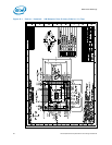
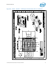
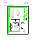
Socket / Heatsink / ILM Keepout Zone Primary Side for 1U (Top) Figure B-1
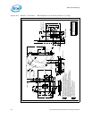
Socket / Heatsink / ILM Keepout Zone Secondary Side for 1U (Bottom) Figure B-2
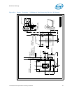
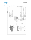
Socket / Processor / ILM Keepout Zone Primary Side for 1U (Top) Figure B-3
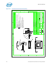
Socket / Processor / ILM Keepout Zone Secondary Side for 1U (Bottom) Figure B-4
1U Collaboration Heatsink Assembly Figure B-5
1U Collaboration Heatsink Figure B-6
1U Reference Heatsink Assembly Figure B-7
1U Reference Heatsink Figure B-8
1U Heatsink Screw Figure B-9
Heatsink Compression Spring Figure B-10
Heatsink Load Cup Figure B-11
Heatsink Retaining Ring Figure B-12
Heatsink Backplate Assembly Figure B-13
Heatsink Backplate Figure B-14
Heatsink Backplate Insulator Figure B-15
Heatsink Backplate Stud Figure B-16
Thermocouple Attach Drawing Figure B-17
1U ILM Shoulder Screw Figure B-18
1U ILM Standard 6-32 Thread Fastener Figure B-19