


LGA1155 Socket and ILM Electrical, Mechanical and Environmental Specifications
38 Thermal/Mechanical Specifications and Design Guidelines
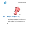
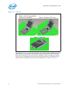
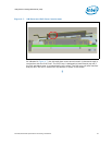
5.3 Loading Specifications
The socket will be tested against the conditions listed in Chapter 11 with heatsink and
the ILM attached, under the loading conditions outlined in this section.
Table 5-3 provides load specifications for the LGA1155 socket with the ILM installed.
The maximum limits should not be exceeded during heatsink assembly, shipping
conditions, or standard use condition. Exceeding these limits during test may result in
component failure. The socket body should not be used as a mechanical reference or
load-bearing surface for thermal solutions.
Notes:
1. These specifications apply to uniform compressive loading in a direction perpendicular to the IHS top
surface.
2. This is the minimum and maximum static force that can be applied by the heatsink and it’s retention
solution to maintain the heatsink to IHS interface. This does not imply the Intel reference TIM is validated
to these limits.
3. Loading limits are for the LGA1155 socket.
4. This minimum limit defines the static compressive force required to electrically seat the processor onto the
socket contacts. The minimum load is a beginning of life load.
5. Dynamic loading is defined as a load a 4.3 m/s [170 in/s] minimum velocity change average load
superimposed on the static load requirement.
6. Test condition used a heatsink mass of 500 gm [1.102 lb.] with 50 g acceleration (table input) and an
assumed 2X Dynamic Acceleration Factor (DAF). The dynamic portion of this specification in the product
application can have flexibility in specific values. The ultimate product of mass times acceleration plus static
heatsink load should not exceed this limit.
7. The maximum BOL value and must not be exceeded at any point in the product life.
8. The minimum value is a beginning of life loading requirement based on load degradation over time.
9. The maximum removal force is the flick up removal upwards thumb force (measured at 45o), not
applicable to SMT operation for system assembly. Only the minimum removal force is applicable to vertical
removal in SMT operation for system assembly.
10. The maximum heatsink mass includes the heatsink, screws, springs, rings and cups. This mass limit is
evaluated using the heatsink attach to the PCB.
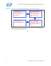
5.4 Electrical Requirements
LGA1155 socket electrical requirements are measured from the socket-seating plane of
the processor to the component side of the socket PCB to which it is attached. All
specifications are maximum values (unless otherwise stated) for a single socket
contact, but includes effects of adjacent contacts where indicated.
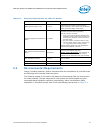
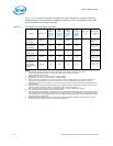
Table 5-3. Socket & ILM Mechanical Specifications
Parameter Min Max Notes
ILM static compressive load on processor IHS 311 N [70 lbf] 600 N [135 lbf] 3, 4, 7, 8
Heatsink static compressive load 0 N [0 lbf] 222 N [50 lbf] 1, 2, 3
Total static compressive Load
(ILM plus Heatsink)
311 N [70 lbf] 822 N [185 lbf] 3, 4, 7, 8
Dynamic Compressive Load
(with heatsink installed)
N/A 712 N [160 lbf] 1, 3, 5, 6
Pick & Place cover insertion force N/A 10.2 N [2.3 lbf] -
Pick & Place cover removal force 2.2N [0.5 lbf] 7.56 N [1.7 lbf] 9
Load lever actuation force N/A 20.9 N [4.7 lbf] in the
vertical direction
10.2 N [2.3 lbf] in the
lateral direction.
-
Maximum heatsink mass N/A 500g 10