


Thermal/Mechanical Specifications and Design Guidelines 63
PECI Interface
7 PECI Interface
7.1 Platform Environment Control Interface (PECI)
7.1.1 Introduction
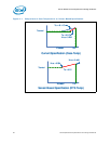
PECI uses a single wire for self-clocking and data transfer. The bus requires no
additional control lines. The physical layer is a self-clocked one-wire bus that begins
each bit with a driven, rising edge from an idle level near zero volts. The duration of the
signal driven high depends on whether the bit value is a logic ‘0’ or logic ‘1’. PECI also
includes variable data transfer rate established with every message. In this way, it is
highly flexible even though underlying logic is simple.
The interface design was optimized for interfacing to Intel processors in both single
processor and multiple processor environments. The single wire interface provides low
board routing overhead for the multiple load connections in the congested routing area
near the processor and chipset components. Bus speed, error checking, and low
protocol overhead provides adequate link bandwidth and reliability to transfer critical
device operating conditions and configuration information.
The PECI bus offers:
• A wide speed range from 2 Kbps to 2 Mbps
• CRC check byte used to efficiently and atomically confirm accurate data delivery
• Synchronization at the beginning of every message minimizes device timing
accuracy requirements.
For single processor temperature monitoring and fan speed control management
purposes, the PECI 3.0 commands that are commonly implemented includes Ping(),
GetDIB(), GetTemp(), T
CONTROL
and TjMax(TCC) read. The T
CONTROL
and TCC read
command can be implemented by utilizing the RdPkgConfig() command.
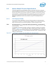
7.1.1.1 Fan Speed Control with Digital Thermal Sensor
Processor fan speed control is managed by comparing DTS temperature data against
the processor-specific value stored in the static variable, T
CONTROL
. When the DTS
temperature data is less than T
CONTROL
, the fan speed control algorithm can reduce the
speed of the thermal solution fan. This remains the same as with the previous guidance
for fan speed control. Please refer to Section 6.1.6 for guidance where the DTS
temperature data exceeds T
CONTROL
.
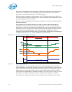
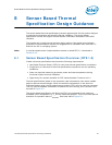
The DTS temperature data is delivered over PECI, in response to a GetTemp()
command, and reported as a relative value to TCC activation target. The temperature
data reported over PECI is always a negative value and represents a delta below the
onset of thermal control circuit (TCC) activation, as indicated by the PROCHOT# signal.
Therefore, as the temperature approaches TCC activation, the value approaches zero
degrees.
§