


Thermal/Mechanical Specifications and Design Guidelines 85
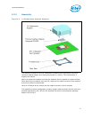
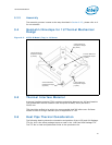
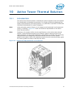
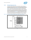
Active Tower Thermal Solution
Note: Diagram does not show the attached hardware for the clip design and is provided only as a mechanical
representation.
10.2.2 Retention Mechanism and Heatsink Attach Clip Assembly
The thermal solution requires a heatsink attach clip assembly, to secure the processor
and fan heatsink in the baseboard socket.
10.3 Electrical Requirements
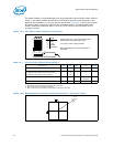
10.3.1 Active Tower Heatsink Power Supply
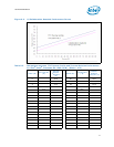
The active tower heatsink requires a +12 V power supply. A fan power cable will be
with solution to draw power from a power header on the baseboard. The power cable
connector and pinout are shown in Figure 10-4. Baseboards must provide a matched
power header to support this. Table 10-1 contains specifications for the input and
output signals at the heatsink connector.
The active tower heatsink outputs a SENSE signal, which is an open- collector output
that pulses at a rate of 2 pulses per fan revolution. A baseboard pull-up resistor
provides VOH to match the system board-mounted fan speed monitor requirements, if
applicable. Use of the SENSE signal is optional. If the SENSE signal is not used, pin 3 of
the connector should be tied to GND.
The fan heatsink receives a PWM signal from the motherboard from the 4th pin of the
connector labeled as CONTROL.
The active tower heatsink requires a constant +12 V supplied to pin 2 and does not
support variable voltage control or 3-pin PWM control.
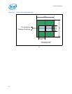
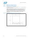
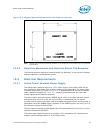
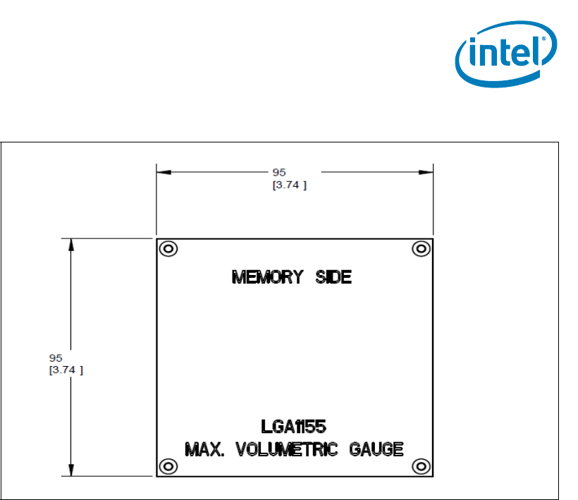
Figure 10-3. Physical Space Requirements for the Solution (top view)