


Viglen SX220 User Guide 20
The 8 pins of the RJ45 connector can be configured to match either of two pin-out
standards used by serial port concentrators. To accommodate either standard, the
J6A2 jumper block located directly behind the rear RJ45 serial port must be
jumpered appropriately according to which standard is desired.
NOTE: By default, as configured in the factory, the SCB2 baseboard will have the
rear RJ45 serial port configured to support a DSR signal.
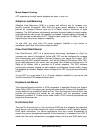
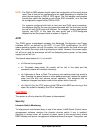
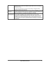
For serial concentrators that require a DCD signal, the J6A2 jumper block must be
configured as follows: The DCD jumper in position 2 and 3 and the DSR jumper in
position 2 and 3. Pin 1 on the jumper is denoted by an arrow directly next to the
jumper block. See Figure 9 on page 129 for the jumper block pin-out of this
configuration.
Figure 6: Jumper Block Pin-out
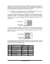
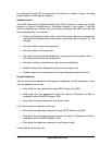
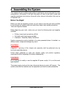
For serial concentrators that require a DSR signal, the J6A2 jumper block must be
configured as follows: The DSR jumper in position 1 and 2 and the DCD jumper in
position 1 and 2. An arrow directly next to the jumper block denotes pin 1 on the
jumper. See Figure 7.
Figure 7: Jumper Clock Pin-out
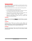
For those server applications that require a DB9 type of serial connector, an 8-pin
RJ45-to-DB9 adapter must be used. The following table defines the pin-out required
for the adapter to provide RS232 support.
Table 3: Pin-out required for an RS-232 support
RJ45 Signal Abbreviation DB9
1 Request to Send RTS 7
2 Data Terminal Ready DTR 4
3 Transmitted Data TD 3
4 Signal Ground SGND 5
5 Ring Indicator RI 9
6 Received Data RD 2
7 DCD or DSR DCD/DSR 1 OR 6
8 Clear To Send CTS 8