Viglen SX220 User Guide 33
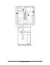
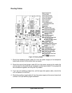
5. Connect the end of the flex circuit cable (C) labeled to the floppy/front panel/IDE
connector on the server board. Route the cable to the backplane board and
connect the opposite cable end to the matching connector on the backplane.
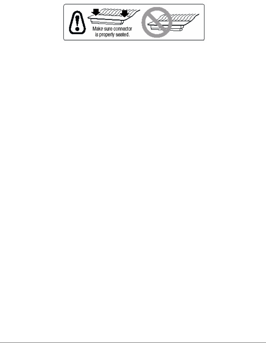
CAUTION!
After connection of cable (C) in step 5, ensure that each cable connector is properly
seated in the board connector. The connector should be parallel to its board
connector and not cocked to one side. If in doubt, remove, reinsert, and recheck.
6. Locate the end of the SCSI ribbon cable (I) that is labeled baseboard. Connect
that end to the SCSI connector on the server board. Route the cable to the
backplane board and connect it to the matching connector on the backplane
board.
7. Route the backplane power cable (A) from the power supply to the backplane
board and connect it to the white 6-pin connector.
8. Connect the front panel cable (E) to the front panel board. Insert the cable in the
cable clip (**), route it to the backplane, and connect it to the matching connector.
9. Connect the USB cable (F) to the USB connector on the server board. Route the
cable along the chassis floor at the bottom of the chassis sidewall (*). Connect it
to the front panel board.
10. Connect the system fan cables (G) to their server board connectors.
11. If you have installed a tape drive, connect the tape drive power cable (D) to the
drive.


