


C-1
Appendix C Host Computer Interface
This appendix explains the signals used in the printer’s parallel
and RS-232C interfaces. It also lists pin assignments, signal
functions, timings, connector specifications, and voltage levels.
The RS-232C protocols are also covered. Finally, it explains how
to use the printer in a multi-computer environment.
This appendix explains the following topics:
• Parallel Interface
• Serial Interface
• RS-232C Protocol
• RS-232C Cable Connection
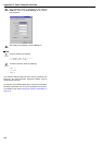
The printer features fast data transmission with the parallel inter-
face. The parallel interface mode can be activated from the op-
erator panel.
See Changing Parallel Interface Modes on page 3-18.
Use a parallel printer cable that complies with the IEEE1284
standard.
Nibble (high) [default]
High speed data communication is used in compliance with the
IEEE1284 standard. Ordinarily, you should leave this setting un-
changed.
Auto
The printer automatically changes its communication mode to
the one the host computer is currently using.
Normal
The printer uses the standard communication method pre-
scribed for Centronics interfaces.
High-speed
This mode enables faster data transmission between the printer
and the host computer. (Select this mode if printing problems oc-
cur when the printer is connected to a workstation.)
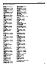
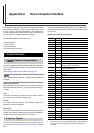
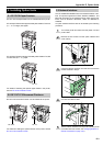
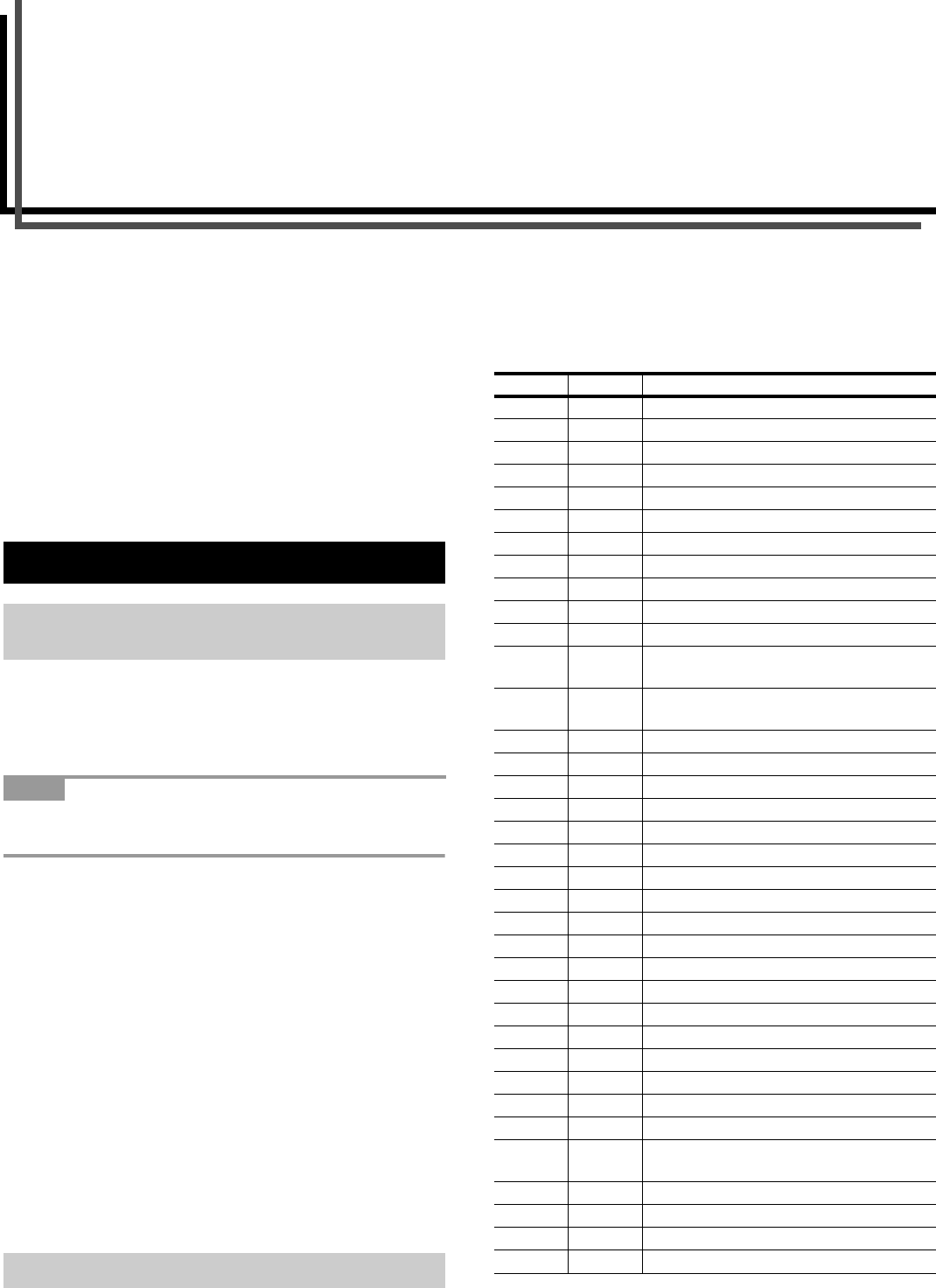
The pins of the parallel interface connector carry the signals list-
ed in the table in Parallel Connector Pin Assignment. Asterisks
in the table indicate signals that are low active. The table also in-
dicates whether each signal is incoming or outgoing with respect
to the printer.
Parallel Connector Pin Assignment
[ ]: Signal names in the Auto mode and Nibble (high) mode (IEEE1284).
In the Auto mode and Nibble (high) mode, these signals are bi-
directional.
1. Parallel Interface
1.1 Parallel Interface Communication
Modes
NOTE
1.2 Interface Signals
Pin In/out Description
1 In Strobe* [nStrobe]
2 In/Out Data 0 [Data 1]
3 In/Out Data 1 [Data 2]
4 In/Out Data 2 [Data 3]
5 In/Out Data 3 [Data 4]
6 In/Out Data 4 [Data 5]
7 In/Out Data 5 [Data 6]
8 In/Out Data 6 [Data 7]
9 In/Out Data 7 [Data 8]
10 Out Acknowledge* [nAck]
11 Out Busy [Busy]
12 Out Paper Empty [PError], returns paper
empty status if FRPO O2=2
13 Out Online (Select) [nSelect], returns off-line
status if FRPO O2=2
14 In Auto-feed [nAutoFd]
15 - Not connected
16 - 0 V DC
17 - Chassis GND
18 - +5 V DC
19 - Ground
20 - Ground
21 - Ground
22 - Ground
23 - Ground
24 - Ground
25 - Ground
26 - Ground
27 - Ground
28 - Ground
29 - Ground
30 - Ground
31 In Ignored [nInit]
32 Out Error*, returns error status if FRPO
O2=2 [nFault]
33 - Not connected
34 - Not connected
35 Out Power Ready
36 In Ignored [nSelectIn]