


Chapter 5. Locating Server Controls and connectors
This section describes the controls, light-emitting diodes (LEDs), and connectors on the front and rear of
the server, and how to turn the server on and off. For the location of the LEDs on the system board, see
“System-board LEDs” on page 112
.
Note: The illustrations in this document might differ slightly from your model.
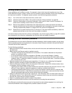
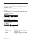
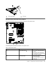
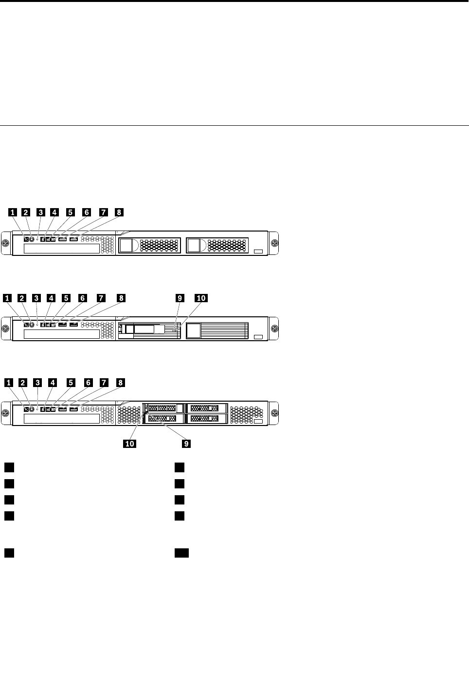
Front view
The following illustration shows the controls, LEDs, and connectors The following illustration shows the
controls, LEDs, and connectors on the front of the various models of the server.
3.5-inch simple-swap SAS server model
3.5-inch hot-swap SAS/SATA server model
2.5-inch hot-swap SAS server model
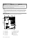
1
Power-on LED
6
System-error LED
2
Power-control button
7
USB 1 connector
3
Reset button
8
USB 2 connector
4
Hard disk drive activity LED
9
Hard disk drive activity LED (green) (on 3.5-inch hot-swap SAS
server model) Hard disk drive status LED (amber) (on 2.5-inch
hot-swap SAS server model)
5
Locator LED
10
Hard disk drive status LED (amber) (on 3.5-inch hot-swap SAS
server model) Hard disk drive activity LED (green) (on 2.5-inch
hot-swap SAS server model)
© Copyright Lenovo 2009, 2010
107