


Universal Serial Bus (USB) port problems
• Follow the suggested actions in the order in which they are listed in the Action column until the problem is
solved.
• See Chapter 7 “Parts listing, RS210 Types 6531, 6532, 6533, and 6534” on page 175 to determine which
components are customer replaceable units (CRU) and which components are eld replaceable units (FRU).
• If an action step is preceded by “(Trained service technician only),” that step must be performed only by
a Trained service technician.
• Go to the Lenovo support Web site at http://www.lenovo.com/support to check for technical information,
hints, tips, and new device drivers or to submit a request for information.
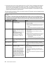
Symptom Action
A USB device does not work. 1. Run USB diagnostics (see “POST” on page 19).
2. Make sure that:
• The correct USB device driver is installed.
• The operating system supports USB devices.
3. Make sure that the USB conguration options are set correctly in the Setup Utility
(see “Using the Setup Utility” on page 197 for more information).
4. If you are using a USB hub, disconnect the USB device from the hub and
connect it directly to the server.
Video problems
See “Monitor problems” on page 54.
Error LEDs
The illustration shows the system-board LEDs. The system board has error LEDs that will help to locate
the source of the error. Run the diagnostic programs to nd out the cause of the error (see “Running the
diagnostic programs” on page 65
).
New graphic to be added in the next draft.
The server is designed so that LEDs remain lit when the server is connected to an ac power source but is
not turned on, provided that the power supply is operating correctly. This feature helps you to isolate the
problem when the operating system is shut down.
Note: When you disconnect the power source from the server, you lose the ability to view the LEDs because
the LEDs are not lit when the power source is removed. Before you disconnect the power source, make
a note of which LEDs are lit, including the LEDs that are lit on the operation information panel and LEDs
inside the server on the system board.
Many errors are rst indicated by a lit system-error LED on the control-panel assembly of the server. If this
LED is lit, one or more LEDs elsewhere in the server might also be lit and can direct you to the source
of the error.
Before you work inside the server to view the LEDs, read the safety information that begins on page
“Important Safety Information” on page 1
.
If an error occurs, view the server LEDs in the following order:
1. Check the control-panel assembly on the front of the server. If the system-error LED is lit, it indicates that
an error has occurred.
2. Check the front and rear of the server to determine whether any component LEDs are lit.
Chapter 4. Diagnostics 61