


3. Remove the server cover and look inside the server for lit LEDs. Certain components inside the server
have LEDs that will be lit to indicate the location of a problem. For example, a DIMM error will light
the LED next to the failing DIMM on the system board. Look at the system service label inside the
side cover of the server, which gives an overview of internal components. This information can often
provide enough information to correct the error.
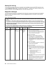
The following table describes the LEDs on the system board and PCI extender cards and suggested actions
to correct the detected problems.
• Follow the suggested actions in the order in which they are listed in the Action column until the problem is
solved.
• See Chapter 7 “Parts listing, RS210 Types 6531, 6532, 6533, and 6534” on page 175
to determine which
components are customer replaceable units (CRU) and which components are eld replaceable units (FRU).
• If an action step is preceded by “(Trained service technician only),” that step must be performed only by
a trained service technician.
Component LED Description Action
DIMM error LEDs
A memory DIMM has failed or is
incorrectly installed.
1. Remove the DIMM that has the lit error LED.
2. Reseat the DIMM.
3. Replace the following components one at a time, in
the order shown, restarting the server each time:
a. DIMM
b. (Trained service technician only) System board
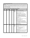
CPU error LEDs
Microprocessor has failed, is
missing, or has been incorrectly
installed.
Note: (Trained service technician
only) Make sure that the
microprocessor is installed
correctly; see “Installing the
microprocessor” on page 141
.
1. Check the system-event log to determine the reason
for the lit LED.
2. (Trained service technician) Reseat the failing
microprocessor
3. Replace the following components one at a time, in
the order shown, restarting the server each time:
a. (Trained service technician only) Failing
microprocessor
b. (Trained service technician only) System board
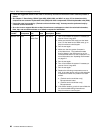
System-board error
LED
System-board CPU VRD and/or
power voltage regulators have
failed.
(Trained service technician only) Replace the system
board.
Battery failure LED
Battery low.
1. Replace the CMOS lithium battery, if necessary.
2. (Trained service technician only) Replace the system
board.
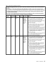
IMM heartbeat LED
Indicates the status of the boot
process of the IMM.
When the server is connected to
power this LED ashes quickly
to indicate that the IMM code
is loading. When the loading is
complete, the LED stops ashing
briey and then ashes slowly
to indicate that the IMM if fully
operational and you can press the
power-control button to start the
server.
If the LED does not begin ashing within 30 seconds
of when the server is connected to power, complete
the following steps:
1. (Trained service technician only) Rerecover the
rmware (see “Recovering the server rmware” on
page 100
).
2. (Trained service technician only) Replace the system
board.
62 Hardware Maintenance Manual