


1
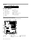
PCI-X power cable
2
PCI-X slot
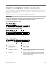
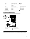
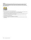
System-board switches and jumpers
The following illustration shows the switches and jumpers on the system board.
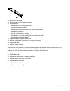
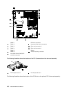
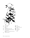
Microprocessor
Heatsink
Orientation
DIMMs
DIMMs
The following table describes the jumpers on the system board.
Table 6. System board jumpers
Jumper number Jumper name Jumper setting
JP1
Clear CMOS jumper 1 • Pins 1 and 2: Keep CMOS data
(default).
• Pins 2 and 3: Clear CMOS data
(including power-on password and
administrator password)
JP6 Boot block jumper 2
• Pins 1 and 2: Boot from primary
BIOS page (default) .
• Pins 2 and 3: Boot from backup
BIOS page.
Chapter 5. Locating Server Controls and connectors 111