Microprocessor
Heatsink
Orientation
DIMMs
DIMMs
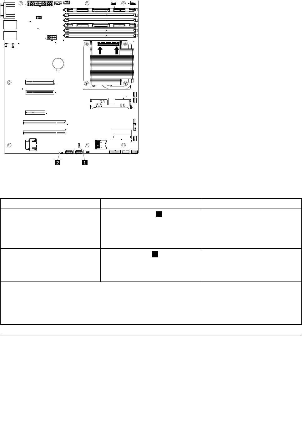
The following table describes the jumpers on the system board.
Table 25. System board jumpers
Jumper number Jumper name Jumper setting
JP1
Clear CMOS jumper 1 • Pins 1 and 2: Keep CMOS data
(default).
• Pins 2 and 3: Clear CMOS data
(including power-on password and
administrator password)
JP6 Boot block jumper 2
• Pins 1 and 2: Boot from primary
BIOS page (default) .
• Pins 2 and 3: Boot from backup
BIOS page.
Notes:
1. If no jumper is present, the server responds as if the pins are set to 1 and 2.
2. Changing the position of the UEFI boot recovery jumper from pins 1 and 2 to pins 2 and 3 before the server is
turned on alters which ash ROM page is loaded. Do not change the jumper pin position after the server is
turned on. This can cause an unpredictable problem.
Using the integrated management module
The integrated management module (IMM) is a second generation of the functions that were formerly
provided by the baseboard management controller hardware. It combines service processor functions, video
controller, and (when an optional virtual media key is installed) remote presence function in a single chip.
The IMM supports the following basic systems-management features:
• Environmental monitor with fan speed control for temperature, voltages, fan failure, and power supply
failure.
Chapter 8. Conguring the server 213


