


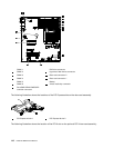
3
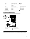
DIMM 3
13
Operator information panel
connector
23
Battery
4
DIMM 4
14
Simple-swap HDD backplane signal
connector
24
Power 2 connector
5
DIMM 5
15
Wake-on-LAN connector
25
Virtual media key connector
6
DIMM 6
16
DVD drive connector
26
Power 1 connector
7
Microprocessor
17
Hypervisor ash device connector
27
Power 3 connector
8
Fan 3 connector
18
Reserved
28
Power 4 connector
9
Fan 2 connector
19
Reserved
29
Fan 5 connector
10
ServeRAD-BR10il
controller connector
20
Reserved
30
Fan 4 connector
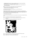
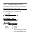
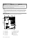
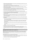
System-board external connectors
The following illustration shows the external connectors on the system-board.
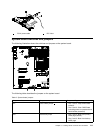
Microprocessor
Heatsink
Orientation
DIMMs
DIMMs
1
Serial (com 1) connector
5
Ethernet connector 2
2
Video connector
6
USB connectors 3 and 4
3
Ethernet connector 1
7
SW1 (NMI button)
4
USB connectors 1 and 2
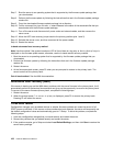
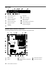
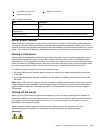
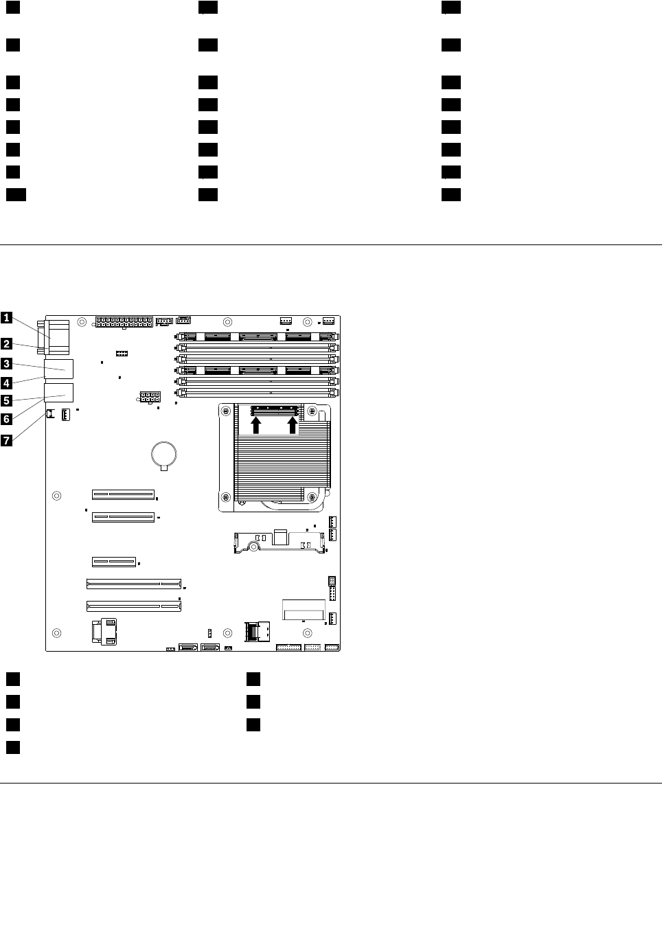
System-board optional-device connectors
The following illustration shows the connectors on the system board for user-installable optional devices.
Chapter 5. Locating Server Controls and connectors 109