


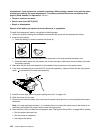
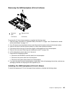
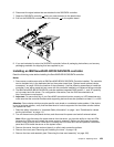
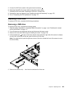

6. Disconnect the signal cables that are attached to the SAS/SATA controller.
7. Grasp the SAS/SATA controller 1 while you press outward on the plastic tabs.
8. Pull out the SAS/SATA controller from the connector 2 on the system board.
9. If you are instructed to return the SAS/SATA controller, follow all packaging instructions, and use any
packaging materials for shipping that are supplied to you.
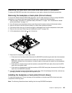
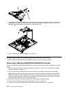
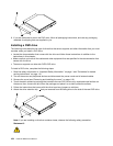
Installing an IBM ServeRAID-BR10il SAS/SATA controller
Read the following notes before installing the ServeRAID-BR10il SAS/SATA controller.
Notes:
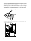
1. Some server models come with an IBM ServeRAID-BR10il SAS/SATA Controller installed. The controller
can be installed only in the dedicated slot on the system board (see “System-board optional-device
connectors” on page 109 for the location of the connector). Use the following procedures to install the
controller if your server model did not come with this controller installed or to replace a failing controller.
2. The IBM ServeRAID-BR10il SAS/SATA controller enables integrated RAID levels 0, 1, and 1E capability
on hot-swap hard disk drives. For conguration information, see the RAID documentation at
http://www.lenovo.com/support.
3. Important: To ensure that any of your ServeRAID controllers function properly on UEFI-based servers,
make sure that the controller rmware and supporting device drivers are updated to at least 11.x.x-XXX.
Attention: Some cluster solutions require specic code levels or coordinated code updates. If the device
is part of a cluster solution, verify that the latest level of code is supported for the cluster solution before
you update the code.
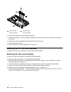
1. Read the safety information in “Important Safety Information” on page 1 and “Guidelines for trained
service technicians” on page 115.
2. Turn off the server and peripheral devices, and disconnect the power cord and all external cables.
Note: When you disconnect the power source from the server, you lose the ability to view the LEDs
because the LEDs are not lit when the power source is removed. Before you disconnect the power
source, make a note of which LEDs are lit, including the LEDs that are lit on the operation information
panel and LEDs inside the server on the system board.
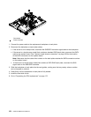
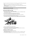
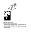
3. Remove the server from the rack and place it on a at, static-protective surface.
4. Remove the cover (see “Removing and installing the cover” on page 119).
5. Remove the riser-card assembly (see “Removing the riser-card assembly” on page 156).
Chapter 6. Replacing FRUs 159