


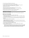
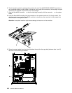
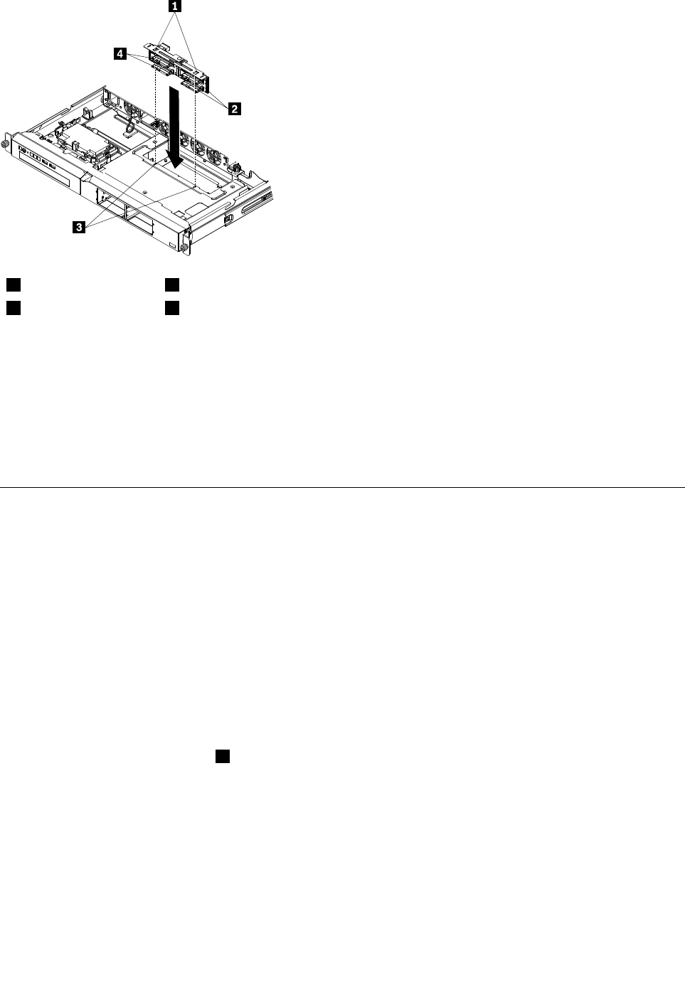
1
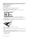
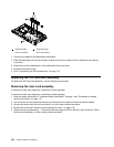
Alignment tabs
3
Alignment slots
2
Drive connectors
4
Drive connectors
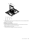
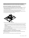
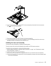
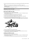
1. Connect the cables to the replacement backplane.
2. Slide the backplane into the card guides, making sure that any nearby wires or cables are not trapped
or pinched.
3. Press rmly until the backplane is fully seated and clicks into place.
4. Install the hard disk drives.
5. Go to “Completing the FRU replacement” on page 172.
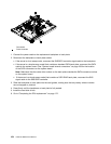
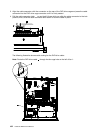
Replacing the PCI riser-card assembly
To replace the PCI riser-card assembly, use the following procedures:
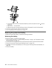
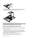
Removing the riser-card assembly
To remove the riser-card assembly, complete the following steps:
To remove the riser-card assembly, complete the following steps:
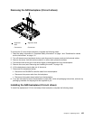
1. Read the safety information in “Important Safety Information” on page 1 and “Guidelines for trained
service technicians” on page 115
.
2. Turn off the server and peripheral devices, and disconnect the power cord and all external cables.
3. Remove the server from the rack and place it on a at, static-protective surface.
4. Remove the cover (see “Removing and installing the cover” on page 119).
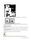
5. Grasp the riser-card assembly 1 at the front and rear edges and lift to remove it from the server. Place
the riser-card assembly on a at, static-protective surface.
156 Hardware Maintenance Manual