


5. Update the server conguration (see “Updating the server conguration” on page 174).
6. Slide the server back into the rack, if necessary.
7. Turn on the peripheral devices and the server.
Connecting the cables
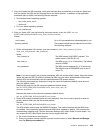
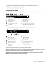
The following illustration shows the locations of the input and output connectors on the front of the server.
1
Power-on LED
6
System-error LED
2
Power-control button
7
USB 1 connector
3
Reset button
8
USB 2 connector
4
Hard disk drive activity LED
9
Hard disk drive activity LED (green)
5
Locator LED
10
Hard disk drive status LED (amber)
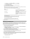
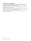
The following illustration shows the connectors and LEDs on the rear of the server.
1
Power-cord connector
9
NMI button
2
Serial connector
10
USB 3-4 connector
3
Ethernet 1 activity LED
11
USB 1-2 connector
4
Ethernet 1 link LED
12
Video connector
5
Ethernet 2 activity LED
13
Power supply error LED (amber)
6
Ethernet 2 link LED
14
DC power LED (green)
7
PCI slot 1
15
AC power LED (green)
8
PCI slot 2
You must turn off the server before you connect or disconnect cables.
See the documentation that comes with any external devices for additional cabling instructions. It might be
easier for you to route cables before you connect the devices to the server.
Cable identiers are printed on the cables that come with the server and optional devices. Use these
identiers to connect the cables to the correct connectors.
Chapter 6. Replacing FRUs 173