


Frame Relay Subinterfaces
13-12 PortMaster Configuration Guide
• Verify that you are using the correct cables and that they are attached securely to
the correct port. Not all WAN ports are capable of the same speeds.
• Verify that the DIP switch is set to V.35 for Lucent cables and that you are plugged
into the correct V.35 interface on your CSU/DSU.
• Verify that the CSU/DSU is providing the clock signal to the PortMaster. The
CSU/DSU can generate the clock signal or receive it from the carrier.
• Verify that the CSU/DSU is configured properly.
• Enter the following two commands to view the LMI or Annex-D keepalives:
Command> set console s1
Command> set debug 0x51
After you verify that the proper keepalives are being received, enter the following
commands to turn off the debug utility:
Command> set debug off
Command> reset console
• If you have a Cisco router on the other end of your connection, verify that it is set
for encapsulation
frame-relay ietf for the serial interface; otherwise, the Cisco
frame-relay map command for your DLCI must have the ietf keyword appended.
Frame Relay Subinterfaces
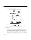
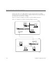
PortMaster routers support a feature called DLCI bundling to allow the splitting of one
synchronous port with multiple DLCIs into a maximum of 32 Frame Relay
subinterfaces. In this configuration, the DLCIs are divided between the subinterfaces
through the use of the location table and the DLCI table. Each subinterface must have
its own subnet or assigned network. The PortMaster has a limit of 512 total active
interfaces, which can be further limited by available memory.
The port you are configuring must be set for network hardwired use and Frame Relay,
and must be in the same dial group as the location.
Configuring Subinterfaces
The following sections describe how to configure a Frame Relay subinterface.