


Chapter 1: 7401-2xxx and 3xxx Product Overview 1-17
When the system is operating in the dimmed display mode, touch
activity can restore full brightness if instructed by software to do so.
When system is in low power mode, touch activity can generate the
mouse port interrupt (IRQ12).
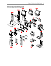
Processor Board Connectors
All connectors are either keyed or impossible to plug incorrectly due to
mechanical design of the product.
External Connectors Internal Connectors
VGA CRT RGB 15 pin D Shell LCD
Ethernet RJ45 Back light Inverter
Dual USB Type A Integrated Speaker Module
External Stereo speaker (3.5mm
jack)
MSR
Power supply Touch screen (PS/2)
RS-232 9 pin D shell (two, one
with +12 V power option)
Integrated Scanner (7401)
PS/2 Keyboard Motion Sensor / Power Indicator
Customer Display PCI Expansion header
Cash Drawer IDE
IRDA Parallel port (POS Board header)
20-pin high density RS-232
Conversion connector
Cash Drawer port (POS Board
header)
Microphone
S-Video
Flash Disk Interface (Discontinued)
The Release 2.0 – 2.5 processor boards provide support for a flash disk
array in the form of an M-Systems DiskOnChip. A 32-pin socket is
provided for this feature. The flash disk must be installed and enabled
in BIOS Setup. This feature is not available on Release 2.5 processor
boards.