Replacing Modules and Filler Panels
3-20 296-1011-202 Rel. 5.0, Doc. Rev. 02.01
CVX 600 Hardware Installation Guide
Reference
For information about the SCC-LTM and SCC-RLTM LEDs, see “Checking the
LEDs” on page 2-43.
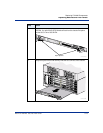
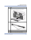
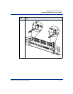
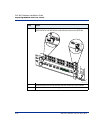
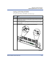
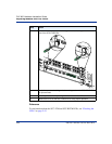
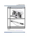
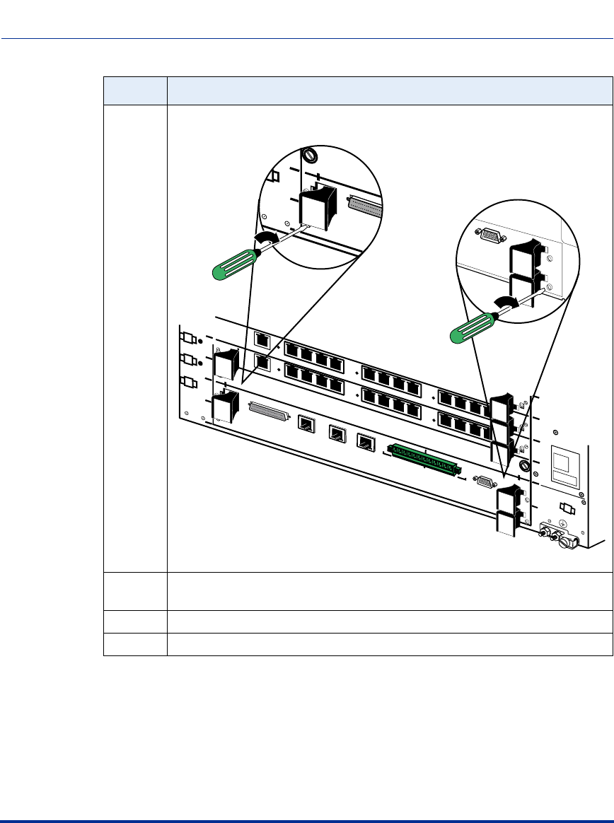
5 Use a1/16-inch flat-tip screwdriver to tighten the four locking screws on the
front of the SCC-LTM/RLTM.
6 Reattach any network cabling and alarm wiring used on the SCC-LTM/RLTM
you just removed.
7 Turn the power back on by turning on the switches on the PDUs.
8 Observe the LEDs on the SCC-LTM/RLTM to verify proper operation.
Step Action
CVX-0157C
3
4
5
6
System
Controller
only
1
2
3
4
Main Chassis
DS3
E 1 x 12
DS1 x 12
Clock
Clock
12
11
10
9
8
7
12
11
10
9
6
5
4
8
7
6
5
3
2
1
4
3
2
1
System Redundant
5
6
4
5
6
System
Controller
only
System Redundant
Console
HSSI
2
Visual
Alarms
Audible
Crit
Ret
Maj
Ret
Min
Ret
Crit
Ret
Maj
Ret
Min
Ret
RX
Link
10/100 Enet
1
RX
Link
10/100 Enet
3
RX
Link
10/100 Enet
DS3
E 1 x 12
DS1 x 12


