


Replacing Modules and Filler Panels
296-1011-202 Rel. 5.0, Doc. Rev. 02.01 3-25
Replacing CVX 600 Components
Reference
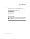
For information about the LEDs, see “Checking the LEDs” on page 2-43.
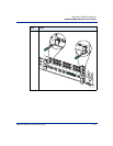
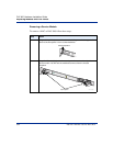
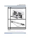
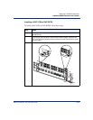
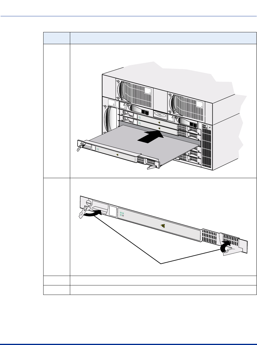
3 Ensure that the latch pawl is in the card guide channel and slide the module
into the chassis until its connector touches the chassis mid-plane.
4 Push the levers inward to fully engage the locking mechanism. The right lever
will click when fully pushed in.
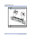
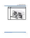
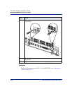
5 Using a 1/4-inch flat-tip screwdriver, turn the locking screw 1/4 turn clockwise.
6 Observe the LEDs on the MAC or DAC-SM to verify proper operation.
Step Action
AC PM
AC PM
Fans
1
2
3
4
5
6
CVX-6oo
BIP
BIP
System
Power
Good
Failed
Redun
Ethernet
HSSI
1
3
2
1
Reset
PCMCIA
1
2
System
Power
Good
Failed
Redun
Ethernet
HSSI
1
3
2
1
Reset
PCMCIA
1
2
DS1
Yellow Red
1
2
3
4
5
6
7
8
9
10
11
12
Power
Good
Failed
Redun
Modem
Power
Good
Failed
Redun
AC PM 1
AC PM 2
PDU 2
PDU 1
ESD
Jack
O
I
O
I
CVX_0160B
Modem/ISDN
Pwr
Good
Fail
Redun
Modem/ISDN
Pwr
Good
Fail
Redun
Pwr
Good
Fail
Redun
CVX_0161C
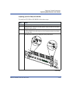
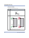
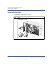
Close ejector levers
Pwr
Good
Fail
Redun