SCC-LTM/-RLTM Interfaces
A-18 296-1011-202 Rel. 5.0, Doc. Rev. 02.01
CVX 600 Hardware Installation Guide
SCC-LTM/-RLTM Interfaces
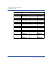
The following table lists the interfaces on the SCC-LTM and SCC-RLTM:
Interface Description
Console • One DB-9 RS-232 serial port
HSSI
(SCC-HSSI-RLTM)
• One port
• 50-pin connector
• Status LED on the SCC-SM for the SCC-HSSI-RLTM
10/100BASE-TX • Switched IEEE 802.3 with autosensing capabilities
• RJ-45 connectors
• MIPS R5000, 64 bit, 180 MHz
• MDI-X
• Full-duplex operation
• Status LEDs on the SCC-SM
Alarms • Up to six independent alarm signals: three audible, three
visual
• Gold-clad silver-alloy contacts
Note: The contacts on the terminal block are rated at 30 VAC
and have a maximum current rating of 1 A. The circuit
connecting the alarms must meet the safety extra-low voltage
(SELV) requirements. The wires connecting the alarms must
be the appropriate gauge for alarm devices.
Clock The following applies to all DAC LTMs with an external clock
port:
• The external clock cicuitry contains a standard T1/
E1 LIU device with receive TIP/RING terminated at
120 ohms (incoming twisted pair).
• T1 clock rate = 1.544 MHz
• E1 clock rate = 2.048 MHz
• Port is hardwired for Bipolar Mode only.
• Port uses B8ZS/HDB3 encoding/decoding.
The external clock port meets or exceeds specifications in
ANSI T1.403 and T1.408; ITU I.431, G.703, G.736,
G.775 and G.823; ETSI 300-166 and 300-233; and
AT&T Pub 62411.


