


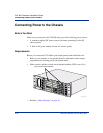
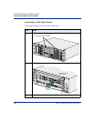
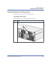
Connecting Power to the Chassis
2-22 296-1011-202 Rel. 5.0, Doc. Rev. 02.01
CVX 600 Hardware Installation Guide
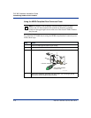
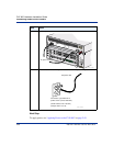
Connecting to a DC Power Source
To connect to the power source, follow these steps:
Step Action
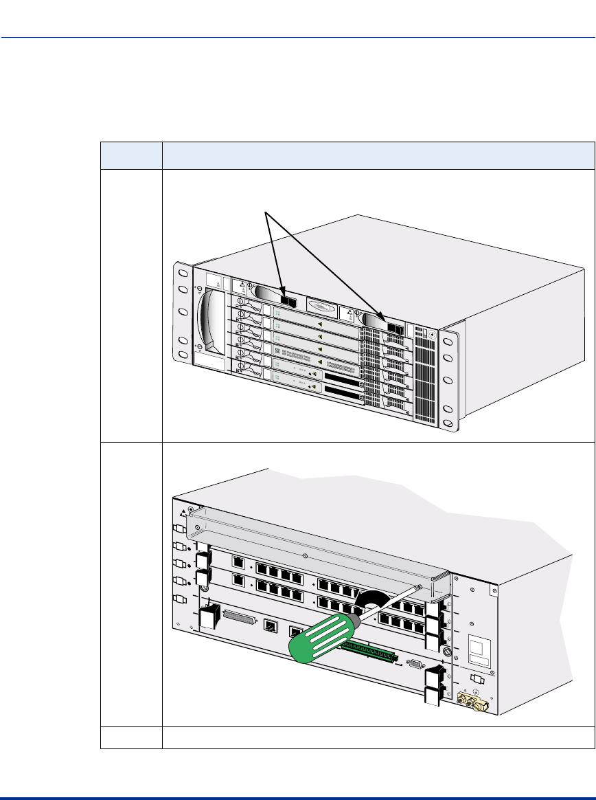
1 Make sure the power switches on the PDUs are off.
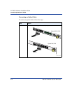
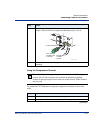
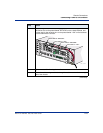
2 Remove the clear cover by removing the three screws on the cover.
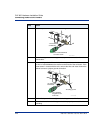
3 Remove the nuts from the posts using a 3/8-inch nutdriver.
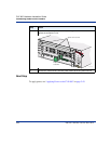
Fans
1
2
3
4
5
6
CVX 6oo
BIP
BIP
Yellow Red
1
2
3
4
5
6
7
8
9
10
11
12
Power
Good
Failed
Redun
PDU 2
PDU 1
ESD
Jack
O
I
O
I
CVX-0202B
Circuit breaker (PDU) switches
Modem/ISDN
Pwr
Good
Fail
Redun
Modem/ISDN
Pwr
Good
Fail
Redun
Modem/ISDN
Pwr
Good
Fail
Redun
DAC DS1x24
Pwr
Good
Fail
Redun
YEL
RED
YEL
RED
3
1
10
11
24
2
12
22
23
21
19
20
18
16
17
15
13
14
9
7
8
6
4
5
System
Pwr
Good
Fail
Redun
10/100 Enet
3
2
1
HSSI
RESET
PCMCIA
1
2
System
Pwr
Good
Fail
Redun
10/100 Enet
3
2
1
HSSI
RESET
PCMCIA
1
2
CVX-0203A
1
2
3
4
5
6
System
Controller
only
1
2
3
4
5
6
Main Chassis
DC PM 2 DC PM 1
DS3
E 1 x 12
DS1 x 12
Tx
Rx
Clock
Clock
12
11
10
9
8
7
12
11
10
9
6
5
4
8
7
6
5
3
2
1
4
3
2
1
System Redundant
Phillips
screwdriver
Turn counterclockwise
to loosen screws.
HSSI
2
Visual
Alarms
Audible
Crit
Ret
Maj
Ret
Min
Ret
Crit
Ret
Maj
Ret
Min
Ret
RX
Link
10/100 Enet
1
RX
Link
10/100 Enet
3
RX
Link
10/100 Enet
Console