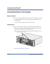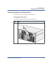
Connecting Power to the Chassis
2-24 296-1011-202 Rel. 5.0, Doc. Rev. 02.01
CVX 600 Hardware Installation Guide
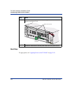
Next Step
To apply power, see “Applying Power to the CVX 600” on page 2-42.
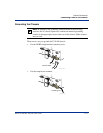
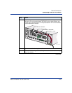
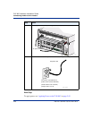
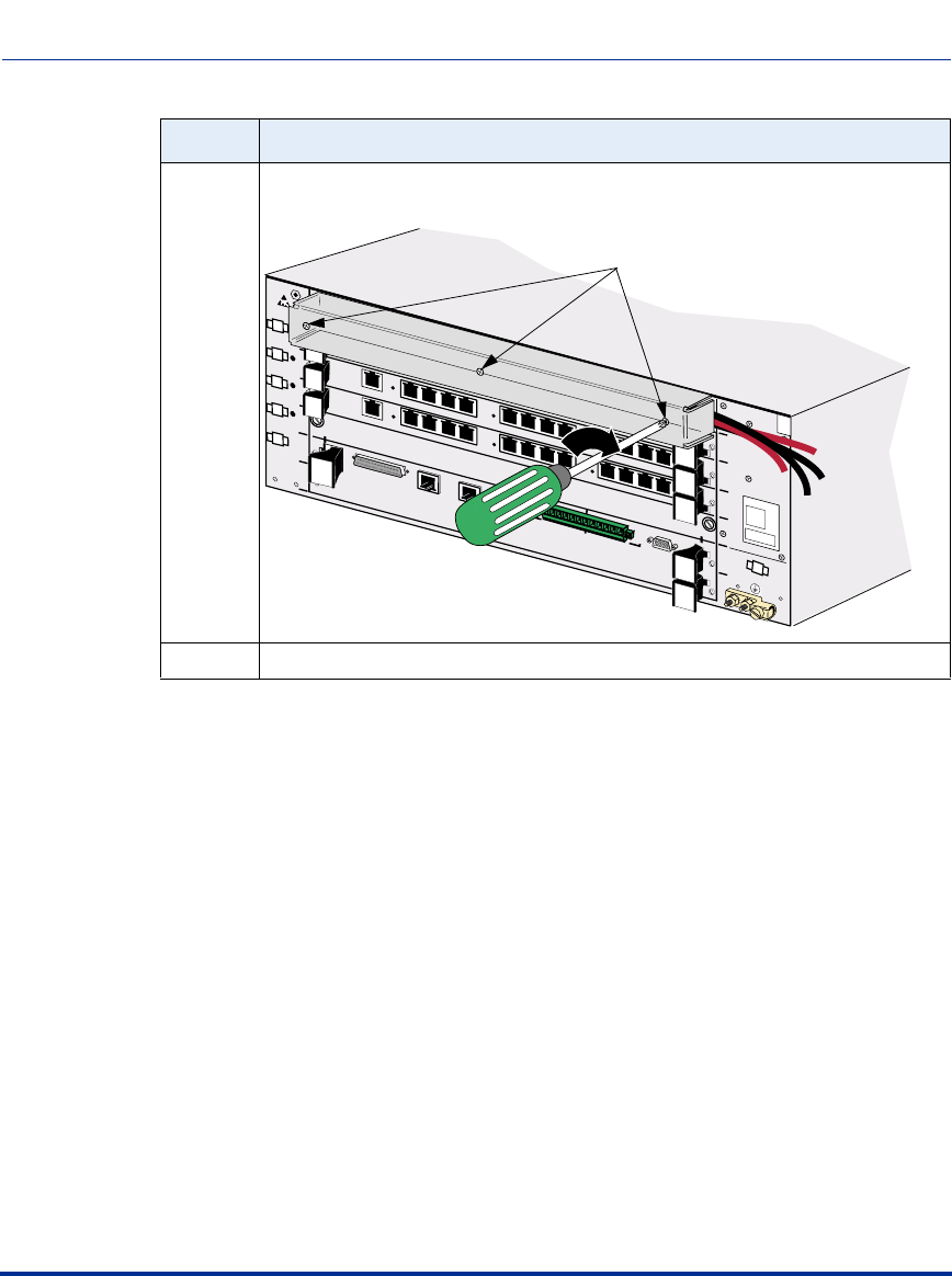
7 Install the clear plastic protective cover, securing the cover with three screws.
Tighten the screws to 6 in-lb.
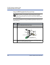
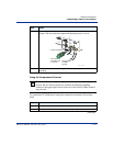
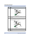
8 Connect the -48V and RETURN DC power cables to the DC power source.
Step Action
CVX-0205A
1
2
3
4
5
6
System
Controller
only
1
2
3
4
5
6
Main Chassis
DC PM 2 DC PM 1
DS3
E 1 x 12
DS1 x 12
Tx
Rx
Clock
Clock
12
11
10
9
8
7
12
11
10
9
6
5
4
8
7
6
5
3
2
1
4
3
2
1
System Redundant
Tighten screws to 6 in-lb.
Phillips
screwdriver
HSSI
2
Visual
Alarms
Audible
Crit
Ret
Maj
Ret
Min
Ret
Crit
Ret
Maj
Ret
Min
Ret
RX
Link
10/100 Enet
1
RX
Link
10/100 Enet
3
RX
Link
10/100 Enet
Console


