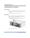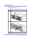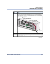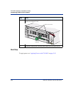
Connecting Power to the Chassis
2-20 296-1011-202 Rel. 5.0, Doc. Rev. 02.01
CVX 600 Hardware Installation Guide
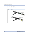
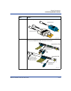
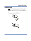
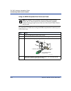
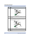
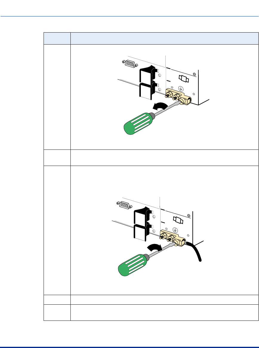
3 Use a flat-tip screwdriver to loosen the locking screw.
4 Use a wire stripper to remove approximately 1/2 inch of insulation from the
ground cable.
5 Insert the stripped end of the wire into the compression terminal; ensure that
the wire is inserted between the retainer and the back of the connector. If the
screw comes in contact with the wire, remove the wire and insert it below the
retainer to ensure a proper ground connection.
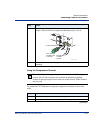
6 Use the flat-tip screwdriver to tighten the locking screw to 24 in-lb.
7 Ensure that the other end of the ground cable is properly connected for frame
grounding.
Step Action
System Redundant
Console
4
5
6
1/4-inch flat-tip
screwdriver
Turn counterclockwise
to loosen screw.
CVX-0225A
System Redundant
Console
4
5
6
1/4-inch flat-tip
screwdriver
To facility ground
Turn clockwise
to tighten screw
to 24 in-lb.
CVX-0246A


