


Principles of Operation
4-493610-A2-GB41-60 March 1999
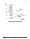
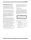
Point-to-Point LADS
Two 3600 Series DSUs that are connected by a 4-wire,
nonloaded metallic pair can support point-to-point LADS
operation. A typical scenario involves two data devices
located in the same building or in a campus environment.
Either the control or the tributary DSU can provide the
internal clock source, or timing can be taken from the
external DTE.
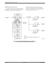
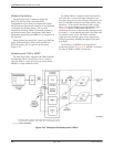
Bridged LADS
A bridged LADS configuration can be used to provide
a multipoint function. Bridged LADS operation at speeds
from 2.4 kbps to 64 kbps is possible through the digital
bridge, which is discussed in the Digital Bridge section of
this chapter. The digital bridge capability is achieved
through the TDM or MCMP circuit card operating in
Bridge mode.
Bridged LADS operation requires the following
hardware (two to six drops):
• One Model 3611 DSU configured as a control.
• One TDM or MCMP circuit card configured as a
digital bridge.
• One Model 3611 DSU per drop at the digital bridge
site. (The 3611 DSUs do not need to be adjacent to
the TDM or MCMP circuit card or even in the same
carrier as the TDM or MCMP.)
If the bridged LADS network is operating at a
speed greater than 19.2 kbps, the distance between
the DSUs and the digital bridge should not exceed
one digital bridge interface cable.
• Digital bridge interface cabling between the digital
bridge ports and the DSUs.
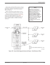
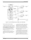
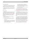
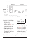
Up to six tributary DSUs can be supported via one
central-site bridge (Figure 4-38). The extended bridges
can be added to extend bridging capability, as explained in
the Digital Bridge section of this chapter, to support up to
31 tributary DSUs.
The digital bridge and DSUs linked via the crossover
cable to the bridge (Figure 4-38) are dedicated to a single
control DSU. Digital bridging of the DTE input/output
signals on Port 1 of the control DSU is performed by the
TDM or MCMP circuit card, which broadcasts Port 1
DTE data to the central-site DSUs and accepts data from
them.
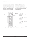
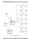
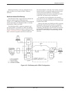
For non-modular Model 3611 DSUs with the digital
bridge capability, a digital bridge interface cable attaches
to the multiport connector on the TDM or MCMP circuit
card to provide fan-out cabling to five individual 25-pin
EIA-232 connectors. For modular Model 3611 DSUs and
Model 3610 DSUs with the digital bridge capability, all
port connectors are individual and a separate crossover
cable is required for each connector. The Digital Bridge/
DSU Interface section of this chapter describes how the
crossover cable completes the communication path
between a digital-bridge port and its associated DSU.