


C-13610-A2-GB41-60 March 1999
Pin Assignments
Overview C-1. . . . . . . . . . . . . . . . . . . . . . . . . . . . . . . . . . . . . . . . . . . . . . . . . . . . . . . . . . . . . . . . . . . . . . . . . .
Overview
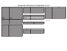
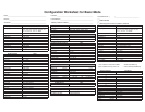
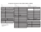
The pin assignments for the 3600 Series TDM and
MCMP connectors and interfaces are included in this
appendix. Refer to them as needed.
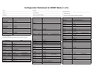
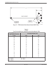
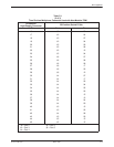
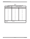
• Figure C-1 shows the TDM interface cable that is
used for both TDM and MCMP non-modular
applications; Table C-1 provides its connector pin
assignments.
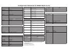
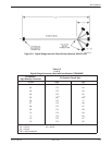
• Figure C-2 shows the digital bridge interface cable
used for non-modular bridging applications;
Table C-2 provides its connector pin assignments.
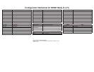
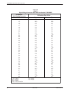
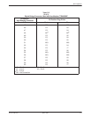
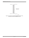
• Figure C-3 shows the pin locations on the
60-position high-density connector of the
carrier-mounted non-modular TDM or MCMP
circuit card; Table C-3 provides its connector pin
assignments.
• Tables C-4 and C-5 provide the EIA-232-D/V.24
and V.35 connector pin assignments for Port 1 for
all DSU-TDMs and DSU-MCMPs.
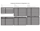
• Figure C-4 shows the V.35 adapter that is used with
the standalone TDM/DSD, MCMP/DSD,
TDM/Flex, or MCMP/Flex models. Table C-6
provides its pin assignments.
• Figure C-5 shows the 6-port connector module used
with the modular TDM and MCMP circuit cards.
Table C-7 provides the EIA-232 TDM and MCMP
connector pin assignments for Ports 2 through 6 for
all standalone and modular DSU-TDMs and
DSU-MCMPs.
• Figure C-6 shows the V.35 interconnect cable used
with the 6-port connector module for the modular
TDM. Table C-8 provides its pin assignments.
Refer to the COMSPHERE 3600 Series Data Service
Units, Models 3610 and 3611, Operator’s Guide and the
COMSPHERE 3600 Series Data Service Units, Models
3610 and 3611, Dial Backup Module and SNA Diagnostic
Interface Options, Applications Guide for additional pin
assignments.
C