


COMSPHERE 3600 Series Data Service Units
5-6 March 1999 3610-A2-GB41-60
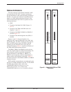
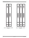
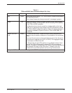
Table 5-2
DSU with TDM or MCMP and DBM-V/DBM-S/DBM-D Status Indicators
Label Color Description
OK Green Health and status indicator. The device’s operation is normal. (The
device has not detected any of the alarms listed in the Alrm section
below.)
This indicator flashes two times per second if a message is present.
Alrm Red Health and status indicator for an alarm in the local or remote device.
For the DSU with TDM or MCMP,
1
the alarm may be in the
communications path between the DSU and TDM or MCMP circuit card.
The following alarms at the local or remote device cause the Alrm status
indicator on the affected device to light: Configuration Corrupt, Device
Alarm, Dial Tone Test Failure, DTE Alarm, Facility Alarm, MUX Failure,
No Response, Redundant Power Alarm, Streaming Terminal,
Subnetwork Alarm, and Out of Frame Threshold.
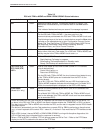
Test Yellow Active device (DSU or DBM-V/DBM-S/DBM-D) is either performing a
test or other units are in Test mode. For a DSU with TDM or MCMP, test
activity may be in the TDM or MCMP circuit card.
2,3,4
Dial Yellow DBM-V/DBM-S/DBM-D is active:
Rapid flashing: Call setup in progress
Slow flashing: Call established but in Standby mode
Steady ON: Backup call established and active
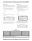
TXD, RXD, RTS,
CTS, DSR, DTR,
LSD
5
Green Internal lead states at DSU-DBM-V/DBM-S/DBM-D-DTE interface
(circuit designations)
:
Control circuit active,
or
Data circuit SPACE(ing).
For the DSU with TDM or MCMP, the circuit external lead states for any
of the TDM or MCMP ports can be selected from the DCP via the
Control branch.
For a 3611 DSU with TDM or MCMP, the port LED illuminated on the
TDM or MCMP faceplate indicates the monitored port. For Model 3610
DSUs, the monitored port is displayed on the DCP’s LED display.
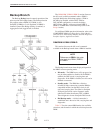
Front Panel
(Model 3611 only)
Yellow Device is currently selected by the SDCP
(the SDCP addresses one
device at a time)
.
For a Model 3611 DSU with TDM or MCMP, the TDM or MCMP circuit
card is also selected
(the TDM or MCMP circuit card has same address
as its associated DSU)
.
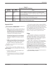
1
Health and status for the TDM or MCMP is integrated into the Health and Status report for the device. For
an alarm in the DSU with TDM or MCMP, this report indicates whether the TDM/MCMP or DSU is at alarm.
2
Any test involving the TDM or MCMP also involves the DSU, and the test is integrated into the DSU’s Health
and Status report.
3
The device is automatically put into Test mode when a remote DSU or DBM is performing a disruptive test
(e.g., a Local Loopback at the control DSU – select LL). A device in Test mode has its DTE interface turned
Off.
4
With a DSU (unless it has an MCMP) or DBM-V/DBM-S/DBM-D running with disruptive diagnostics, this
LED will flash each time a diagnostic poll or response is received.
5
When a TDM or MCMP is installed, DTR will always appear as ON for Port 1. Refer to the DTE Status
display on the DCP to determine the state of the DTR lead.