


Principles of Operation
4-373610-A2-GB41-60 March 1999
For non-modular Model 3611 DSUs with digital bridge
capability, a digital bridge interface (crossover) cable
attaches to the 60-pin high-density connector on the TDM
or MCMP circuit card to provide fan-out cabling to five
individual 25-pin EIA-232 connectors. Since a digital
bridge port provides a DCE interface, and the digital
bridge port connects to equipment that also provides a
DCE interface, the crossover function is provided by the
digital bridge interface cable, which must be provided
between the two DCE interfaces to present the data and
control leads on the proper pins. The pin assignments for
this cable are provided in Appendix C.
For modular Model 3611 DSUs or Model 3610 DSUs
with the digital bridge capability, all port connectors are
individual, requiring a separate crossover cable for each
bridge port.
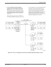
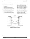
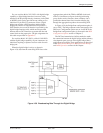
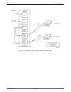
When the digital bridge is active, as shown in
Figure 4-30, data from the controlling DTE flows to the
aggregate data path of the TDM or MCMP circuit card,
where it is broadcast to all ports in the digital-sharing
group. In the receive direction, when a tributary site is
granted the channel, data flows from the tributary site
through the aggregate data path to the controlling DTE.
In Figure 4-30, the Bridge Rate configuration option is
set to =DSU. The bridge operates at the same speed as the
DDS core. Configuration options are set via the DCP; the
Bridge Rate configuration option is discussed in the MUX
Configuration Options section of Chapter 5.
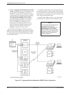
The DCE and transmission facilities needed to make
the connection between the digital bridge and the tributary
sites depends upon your use of the digital bridge. Many
applications are possible. Three applications are discussed
in the Multichannel Multipoint, Multipoint Dial Backup,
and LADS Operation sections of this chapter.
Figure 4-30. Broadcasting Data Through the Digital Bridge