


COMSPHERE 3600 Series Data Service Units
5-46 March 1999 3610-A2-GB41-60
When in TDM or MCMP mode, the selections are 1, 2,
3, 4, 5, 6, or Aggr. Aggr is the communications interface
between the aggregate data path (on the TDM or MCMP
circuit card) and the DSU. In Bridge mode, the selections
are 1, 2, 3, 4, 5, 6, or DCE. DCE is the communications
interface between Port 1 (on the TDM or MCMP circuit
card) and the DSU; Port 1 is the aggregate link to the
DTE, while Ports 2 through 6 may be connected to
DBM-Vs, DBM-Ss, or DBM-Ds.
Refer to the TDM Architecture and Digital Bridge
sections of Chapter 4 for additional information.
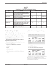
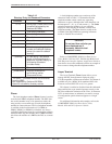
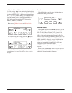
F1 F2
F3
LEDs Port: 2
Undo
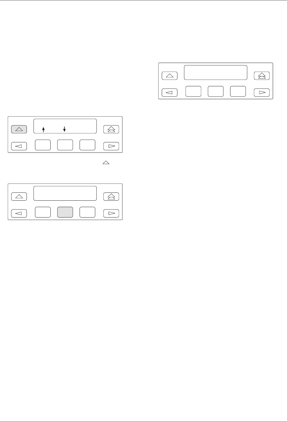
To continue with your change, press the
key to
return to the Load/Save menu selections.
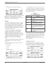
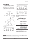
F1
LEDs Port:
Load Save
F2
F3
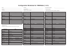
Press the F2 (Save) key to change the monitored port to
a new selection. You must select Save to have the entry
accepted.
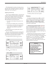
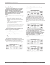
Results
The DSU displays the following, indicating that the
command has been put into effect.
F1
Save LEDs Port: 2
Command Complete
F2
F3
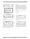
External Leads
Through the External Leads (ExtL) selection, you can
display the state of four general-purpose leads on the
EIA-232-D/V.24 Port 1 interface: Pins 12 and 13 for
output (control leads) and Pins 19 and 23 for input (alarm
leads). If the configuration option External Leads (Ext
Leads) is set to ExtLd, you can change the state of the two
output leads from the DCP or from a 6700 or 6800 Series
NMS. If the DSU’s diagnostic protocol is ADp and the
CCN by External Leads (CCN by EL) configuration
option has been enabled, a control DSU reports any
changes to the four leads to the 6700 or
6800 Series NMS as part of its health and status poll
response.
Refer to the COMSPHERE 3600 Series Data Service
Units, Models 3610 and 3611, Operator’s Guide for
additional information and for examples.